that was a nice exlpanation andrew. i was hoping to make a microcontroller controlled protect circuit from apex circuit. so far apex give me informations how the circuit work. my main concern is, does the microcontroller make a noise interference to the amplifier? it would run at 4mhz internal oscillator.
Diyers don't like protections. I think quad OP with several transistors is already to much for diyers. This amplifier with OP amp in input stage also not popular like 'school book' amps.
Regards
hello apex i have an 8amps transformer salvaged from a junk amplifier. secondary ac is only 45-0-45. i only get around 60 volts on dc. is this enough to make the b500 work?
regards
julius
regards
julius
hello apex i have an 8amps transformer salvaged from a junk amplifier. secondary ac is only 45-0-45. i only get around 60 volts on dc. is this enough to make the b500 work?
regards
julius
B500 will work with +/-60V DC, just use 2k2/2W for R24 and r25.
Regards
Add step driver with TL072 to B500, you can use PSU from H900, and you get class H amp with same power as H900.
thanks to this crown design step driver
even IR2117 is not available here
i can still pursue my first CLASS H
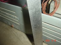
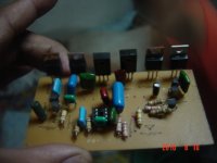
see old casing prepared for new class h amp almost only 5'' in height
that was an old amp and casing
Attachments
Step driver with TL072 instead with IR2117, and many diyers will be hapy and greatfull 🙂
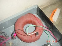
i have to rewire the trafo i need to add 2x40v and 2x18v
Attachments
hi engel dela pena
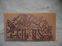
greetings coincidence i am making same pcb for my new amp but using
tlo 72 step driver pcb
thanking you
andrew lebon
greetings coincidence i am making same pcb for my new amp but using
tlo 72 step driver pcb
thanking you
andrew lebon
i have to rewire the trafo i need to add 2x40v and 2x18v
i think you need 4x40 and 2x18
hello mate,^^ ohh you want to add 2x40 and 2x18 to the existing traffo :=) thats fine.
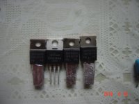
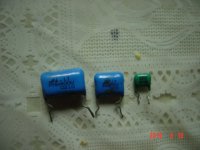
please check this one,is Ou1 rated400v in the center the blue one,
is this fine(400v)?
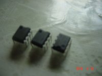
and i used bc547b,instead of 546,
is this fine also?
thats what i have in stock.
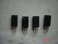
and the BF 422/423 their replacement is MPSA92/93 but when i purchase MPSA the marking is diff. it is ksp92 &ksp93
is this fine?
Attachments
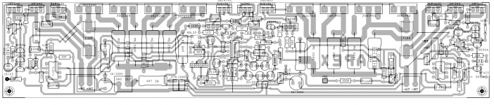
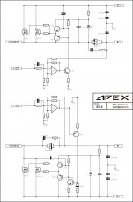
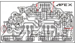
hello mate,Apex can you check any problem. this is base on schematic you provide not the landscape pcb. B500 to H900 using TL071
here it is TLO72
Attachments
![APEX%20Hclass%20Power%20DriverMON[1].jpg](/community/data/attachments/167/167647-e4758819b6a6fbb23f402828618b49e2.jpg?hash=5HWIGbam-7)
hello mate,
here it is TLO72
Component layout have mistake 47pF is notification as 0u1. ZF10 and 10uF on negative side wrong direction, sorry.
BF422/BF423 can be replaced with MPSA42/MPSA92, but different pin layout.
Regards
Attachments

Last edited:
thank you apex,Component layout have mistake 47pF is notification as 0u1. ZF10 and 10uF on negative side wrong direction, sorry.
BF422/BF423 can be replaced with MPSA42/MPSA92, but different pin layout.
Regards
47pf
i was thinking all caps noted in 47 is in nf,so it was also my mistake,
should i have to change them?47pf(682) is not same as 47nf(473)
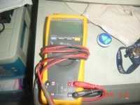
i was about to enjoy my new true rms 177,cheking caps in nf from old pcb's from pc monitor and fit it to tlo step driver,sadly pf is out of it's reach
Attachments
Last edited:
thank you apex,
47pf
i was thinking all caps noted in 47 is in nf,so it was also my mistake,
should i have to change them?47pf(682) is not same as 47nf(473)
i was about to enjoy my new true rms 177,cheking caps in nf from old pcb's from pc monitor and fit it to tlo step driver,sadly pf is out of it's reach
You can see all component values on step driver schematic.
47 is 47pF
682 is 6,8nF
473 is 47nF
Regards
hi apex, have you check post #570? is it nescessary for offset setting of TLO71?
I just see post #570, congratulation great job. I must check. No nescessary for setting offset of TL071.
Thank you for your work, I'm sure your pcb design will be usefull for many diyers.
Regards
- Home
- Amplifiers
- Solid State
- 500W PA amplifier with Limiter