Shipping Issue's
Dear Forum members,
From today i can ship now via a Chinese company that uses Hong Kong post.
The packages can be shipped out as usual with the same shipping time as before, around 2 weeks to anywhere in the world.
Shipping cost have gone up alittle bit, minimal charge is 10 Euro per shipment for max 350 Grams. anything above that i will have to calculate at request.
The cost rise a bit, but these packages are insured and have a tracking number for online tracking at www.hongkongpost.com
Also i have made an Exel list with items that any DIYer could use well. if you would be interested, drop me a mail at Arjenhelder@hotmail.com and ill reply you with the list.
Greetings,
Arjen Helder.
Boards arrived fine, thanks Arjen. And thanks to your girlfriend, they were very well packed.
Can you give me details for the input connector, I guess it's something like L, GND, R, or similar? thanks.
Can you give me details for the input connector, I guess it's something like L, GND, R, or similar? thanks.
Hey there, yes it is, but at the moment i have no boards! as soon as i have stock i wil post it here!
Greetings,
Arjen Helder
Greetings,
Arjen Helder
TA2024 boards
Hi Arjen,
from zelfbouwaudio site I found out you seem to have these little T2024 monsters again. Confirmed?
Unfortunately I have not enough posts here to PB you.
so please email me instead
Thanks.
Hi Arjen,
from zelfbouwaudio site I found out you seem to have these little T2024 monsters again. Confirmed?
Unfortunately I have not enough posts here to PB you.
so please email me instead
Thanks.
New lot found
Dear all,
I have now got a new lot of PCB's, about 100 of them so for whoem ever is interested, there ready for order and still cost 5 Euro per board
Also i have got the TA2020 board now! this board costs 20 Euro and has 25 Watts from a 12 volts supply, smps are also available. ( 12 volts 6,4 A )
Dear all,
I have now got a new lot of PCB's, about 100 of them so for whoem ever is interested, there ready for order and still cost 5 Euro per board
Also i have got the TA2020 board now! this board costs 20 Euro and has 25 Watts from a 12 volts supply, smps are also available. ( 12 volts 6,4 A )
On bike system
Hi guy's
since you guy's asked what kind of amp would be best for on a bike, ive been searching around to see what a efficient small and high power amp could be best suited... ive looked at car amps, but there so hungry you also need a car battery, ive looked at TDA8920 and TA2022 but they need 25+25 volts... not so conveniant ive also looked at classical TDA solutions as the TDA3020 but they lack power and eficancy.
The TA2020 i have in stock here i think can do the job, if you use 4 Ohms speakers. ive got 10 Ohms speakers in my house, and they rock! with this little 12 volts amp it really go's loud! im sure that if you can get high efficent speakers, 25 watt's can be enough for a booming ride.
I can supply these PCB's for 20 euro each, they are stereo and compleatly finished, and have build in protection, weigh a mere 80 grams!! and are of small size! on request i can also supply you with battery brackets for D cells and rechargable D cells
( those cost 5 USD each and are 1,2 V 8 A!!)
i think that is a good solution for a price that can't be beaten!
Greetings,
Arjen, Shenzhen, China.
Attachments
Hi Arjen,
I am interested in your TA2020 board. Would you please let me know the cost to ship this amp to Vietnam?
I am interested in your TA2020 board. Would you please let me know the cost to ship this amp to Vietnam?
TA2020
Hi there wireland,
Yes fully finished PCB including IC and all other components.
All you need is a 12 volts powersupply and a audio signal!
If you want these, mail me @ Arjenhelder@hotmail.com
Ive tested these PCB's for a couple of weeks and do enjoy there sound.
Greetings,
Arjen Helder
Hi there wireland,
Yes fully finished PCB including IC and all other components.
All you need is a 12 volts powersupply and a audio signal!
If you want these, mail me @ Arjenhelder@hotmail.com
Ive tested these PCB's for a couple of weeks and do enjoy there sound.
Greetings,
Arjen Helder
Just thought I'd comment that I have received 4 boards from Arjen. They arrived very quicly and were well packaged. Arjen (and his girlfriend) is a very helpful and friendly person to deal with too.
Boards are really amazing for the money. I really dont think better bang for buck exists than these. PCBs are surprisingly good quality and the amps sound good - they even come with film input caps (though they should probably be changed anyway).
Many thanks Arjen
Boards are really amazing for the money. I really dont think better bang for buck exists than these. PCBs are surprisingly good quality and the amps sound good - they even come with film input caps (though they should probably be changed anyway).
Many thanks Arjen
Thanks
Thanks Valleyman, Just doing what i think is best 🙂
The caps are best changed, this also counts for the buffer caps, there a tad bit small, if you want better capacitors with the set, ive got those and there cheap.
Greetings from Hongkong ( im here for 3 days )
Arjen Helder
Thanks Valleyman, Just doing what i think is best 🙂
The caps are best changed, this also counts for the buffer caps, there a tad bit small, if you want better capacitors with the set, ive got those and there cheap.
Greetings from Hongkong ( im here for 3 days )
Arjen Helder
quick delivery
Last week I was telling the boys at work about Arjen's amps and today they showed up. I received two 2024 boards along with mod kits. They were well packed, Thank you Arjen!
Can anyone point me to posts that show where to put the caps and resisters?
and one more question.... the input has 3 connectors, is the middle one common?
thanks for the help,
Mack
Using the TA2024
Hi there Mack, glad everything is in a good state,
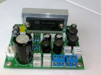
The Audio input is the White connector in the board, the middle is GND, so te common, as you call it and the left and right pins are for left and right input.
The filter capacitors are the larger black tubes with a bubble on them ( there actually a film cap and a electrolytic cap biggy back )
These can be removed and replaced by other input capacitors. ( the yellow ones saying 225 - 400V )
The Buffer caps, Best to remove the 2 caps on the PCB (470uF 25 volts ) so you can eazely solder the wires to the board.
If you can get a hold of some solder wick ( copper wire that sucks up the molten solder ) or a de-solder pump, then you can eazely remove the remaining solder from the PCB holes.
Best is to take some thicker wire, say 1 mm in thickness and solder those to the buffer capacitor if you carefully watch the polarity, nothing can go wrong.
Good luck!
Arjen Helder
Shenzhen CHina
Hi there Mack, glad everything is in a good state,
The Audio input is the White connector in the board, the middle is GND, so te common, as you call it and the left and right pins are for left and right input.
The filter capacitors are the larger black tubes with a bubble on them ( there actually a film cap and a electrolytic cap biggy back )
These can be removed and replaced by other input capacitors. ( the yellow ones saying 225 - 400V )
The Buffer caps, Best to remove the 2 caps on the PCB (470uF 25 volts ) so you can eazely solder the wires to the board.
If you can get a hold of some solder wick ( copper wire that sucks up the molten solder ) or a de-solder pump, then you can eazely remove the remaining solder from the PCB holes.
Best is to take some thicker wire, say 1 mm in thickness and solder those to the buffer capacitor if you carefully watch the polarity, nothing can go wrong.
Good luck!
Arjen Helder
Shenzhen CHina
Arjen, you reply as quickly to email as you ship goods. Two more questions if I may.
Where do the trim pots go, C9 and C10?
You included several resisters. I can't find a reference to them in the thread.
I forgot to ask you about power supplys. I think I've seen you use 12v 2a units. Are they big enough for these amps? Do you sell them?
Sorry for all the questions.
Mack
Where do the trim pots go, C9 and C10?
You included several resisters. I can't find a reference to them in the thread.
I forgot to ask you about power supplys. I think I've seen you use 12v 2a units. Are they big enough for these amps? Do you sell them?
Sorry for all the questions.
Mack
questions
Hey there Mack, no worries, here to help.
This is the Mod as described by ElFishi, one of the DIYaudio members from Germany:
Arjen's board:
for orientation put the board in front of you such that IN faces left and OUT faces right.
I use two 10k standing miniature trim pots
One goes right above the IN socket. Its left end is soldered to the ground rail, its right end is soldered to the left end of C17.
The center pin goes to the left end of R5 via a 1MOhm resistor.
The second pot sits right under the IN socket. The left end is again soldered the the ground rail. The right end I connected to the right end of the first pot via an insulated wire.
Center pin goes to the left of R6, again via a 1MOhm resistor.
You can find this information on Page 21 of the sure boards thread
Powersupplies are available, i have now got 12 volts 2 A and 12 volts 3 A the 2 A is 10 euro and the 3 A is 12 euro.
With the 10.000uF buffer caps, not to worry, plenty of juice to go round! if you want to test for that, use a oscilloscope on the power pins, and play loud music with the PCB. if you can see large voltage drops, power is insuffiecent.
If you like it loud, i do suggest some kind of heat sink to the top of the IC. ive used 2 component glue for that before, to a small piece of aliminium. works like a charm.
Greetings,
Arjen Helder
Tilroh Wrote: Where do the trim pots go, C9 and C10?
You included several resisters. I can't find a reference to them in the thread.
Did you check the DC offset on your boards.?? You may allready have a low DC offset & not need to install the trimmers.
You can easily check the DC content of each channel output with a multimeter. You should do this with no input & measure at full volume.
Typically my 4 boards were all in the 12 > 25 mV range & I considered these not worth modifying in this area.
Tripath specify a DC offset as typically 50mV, maximum 150mV in their data sheet. Personally, in my opinion 150mV is far too high & I would only modify them if over 50 mV.
As everyone has stated, these boards of Arjen's perform very nice with minimal modifications.
" don't fix it, if it aint broke"
Paul
DC offset - poping on power up
Thanks ZL2BPS,
I'd certainly not change anything that doesn't need it. I probably can't hear the different anyway.
My 2024 Sureelectronics boards pop on power up and on shut down. Would this be a symptom of too much DC offset?
Thanks guys,
Mack
Thanks ZL2BPS,
I'd certainly not change anything that doesn't need it. I probably can't hear the different anyway.
My 2024 Sureelectronics boards pop on power up and on shut down. Would this be a symptom of too much DC offset?
Thanks guys,
Mack
- Status
- Not open for further replies.
- Home
- Vendor's Bazaar
- 50 RMB( 5,- EUR ) Tripath TA2024 PCBA's