Planet 10,
do you know how essential it is, for the drivers to be mounted aligned, on-axis?
It could be tempting to mount the drivers with an off-set, therby using the space between the front woofers' magnets to accomodate the magnets of the "hidden" woofers. Considering the depth of the structures, this could save 10cm in the depth.
I don't want the "hidden drivers" to be placed too near the rear wall of the "overall" cabinet.
As long as it's a sealed volume of air being moved my the drivers (in the isobaric chamber), alignment shouldn't be important in my imagination (?)...
Any comments?
Jennice
Originally posted by Jennice
do you know how essential it is, for the drivers to be mounted aligned, on-axis?
It could be tempting to mount the drivers with an off-set, therby using the space between the front woofers' magnets to accomodate the magnets of the "hidden" woofers. Considering the depth of the structures, this could save 10cm in the depth.
Basically, the small the coupling chamber the better... with 4 woofers i'd mount them similar to my drawing above, which means 2 chambers.
dave
Hi Dave,
I see your point, and I don't like to "waste" more enclosure volume than needed, but the speakers will be in a room with two small children (technical hazard) and a spouse (aestetical hazard if she doesn't like 'them). Thus, I don't think I can get away with two "free" speakers like you have on the outsides of your drawing.
While we're at it... If I recall correctly, you have shown several projects where you compensate for baffle step loss with an extra driver on the rear. This baffle step is 6dB, right?
Jennice
azrix said:As far as I know, you have that correct. You should gain 3db for doubling cone area once (2 drivers), another 3db for doubling again (4 drivers), and none from impedance since that didn't change. Which gives you a 6db net gain.
I have to recant this. You do only gain 3db at 1watt when you double your drivers, but it's not because of cone area, it's because you double your Vas, and doubling Vas gets you a 3db boost in efficiency. Doubling displacement (cone area) gives you a 6db boost in total output. So, given two of the same driver wired in parallel, you should have a 3db boost in efficiency due to increase in Vas, and doubling of power handling, which also gives you a 3db boost if you have enough power, giving you a 6db total boost, but at half the impedance.
With regard to driver arrangement, there are a million different ways you could do it and I don't know how small you want your speakers. I personally would consider having all four drivers, one on top of the other, on the front baffle, but that would be getting close to one meter tall just for the bass drivers. May be too big for you. Baffle step is a bit tricky. If you are building a floor standing speaker and have your bass drivers very close to the floor, then you should not need any baffle step since your bass speakers will be radiating into a half-space just like your mid and tweeter. You can also cross over to the bass drivers at baffle step and use the increase in efficiency of having multiple drivers counteract the decrease you get from baffle step.
That's nice, but I heard there is some thermal problems associated with the outside woofers because the chamber is so small. Did you hear about this planet10 ?
Originally posted by simon5
I heard there is some thermal problems associated with the outside woofers because the chamber is so small.
There could well be... i a home hifi situation, it probably is not too serious.
dave
Hi,
you quoted some box volumes for 1 & 4 drive units.
41L for 1 & 164L for 4; giving 82L for 2.
In isobaric format double the number of drive units and half the volume. Now you have double the power handling but the same Xmax.
Taking the 82 litre box with 2 drivers then go isobaric and have 4 drivers with 4 times the power handling and same Xmax in a 41L box (too small to be worth the effort). and gaining 3db in efficiency. (90db?? can someone confirm).
I have simply restated what has gone before in case you missed the points being made.
The problem may be that you run out of cone travel at low frequency (same Xmax) but I think the volume(SPL) by then will be deafening.
Does all that make sense?
Officially, the 4 x isobarik box will give me the same output (ignoring impedance effects on the amp(s)) as a pair in a box 2x as big.
Power handling is something that i have no concern about. Besides the smaller box, i get the mass trapped between the 2 drivers to lower the Fs subtely, the extra layer of cone to isolate what happens in the box from outside the box, and the push-pull-push-push motor which will not only reduce vibration passed to the box, but will help linearize the drivers over a single example. I lose the air the extra 4 drivers would move, but i think 4 12" in my room will be more than sufficient.
As was recently pointed out in one of the threads, increasing the number of drivers doesn't actually increase efficiency (flying in the face of common knowledge i had to go back and look at it from 1st principals to see that this is probably true (ignoring potential gains from improved coupling with the air))
dave
I have studied various pictures of isobaric designs... is it correctly understood, that minimizing the volume of air between the isobaric pair is important (which could be why most make them front-to-front mounted)?
Jennice
Jennice
Front to front will always be the best, better coupling between drivers, better thermal dissipation, closer to the simulated response...
But then, not everyone like to look at a steel basket and some might be afraid of easy damage done by people since the basket is exposed.
But then, not everyone like to look at a steel basket and some might be afraid of easy damage done by people since the basket is exposed.
Originally posted by Jennice
is it correctly understood, that minimizing the volume of air between the isobaric pair is important (which could be why most make them front-to-front mounted)?
Yes, smaller is better. The smaller chamber has less compliance in the trapped air so that you have better coupling and the resonant structure of the coupling chamber is pushed up in frequency.
dave
Hmmm.. this makes sense.
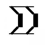
I was originally hoping for the concept chown on my attachment, but I realize that it encloses a lot more air than the "front-to-front" aproach. My idea would have a higher spouse acceptance factor, but would probably not be as good in performance.
Also, I understand that the volume between the drivers has to be very well sealed. Any suggestions on what to use? Silicone gives a nice seal, but makes it impossible to remove anything once mounted.
I fon't really know any alternatives, though.
Jennice
Attachments
Originally posted by Jennice
I was originally hoping for the concept chown on my attachment, but I realize that it encloses a lot more air than the "front-to-front" aproach
That is the way Linn did it ... it also means you don't have to worry about the junk raditing off the frame of the driver (ie you can go higher.
My idea would have a higher spouse acceptance factor, but would probably not be as good in performance.
Also, I understand that the volume between the drivers has to be very well sealed. Any suggestions on what to use? Silicone gives a nice seal, but makes it impossible to remove anything once mounted.
I just use standard seled box procedures -- foam draft seal tape.
dave
planet10 said:
I just use standard seled box procedures -- foam draft seal tape.
dave
I learned my lesson about silicone the hard way... and that's why I'm looking for alternatives. Are you referring to the kind of foam strip with adhesive tape on the back, to put on window frames etc. to seal against wind? (Sorry if my question seems dumb, but it's a language thing
 )
)Jennice
Originally posted by Jennice
Are you referring to the kind of foam strip with adhesive tape on the back, to put on window frames etc. to seal against wind?
Yes... comes in lots of widths, thickness, & densities. It seems to have a million names... i usually say "draft exclusion tape" but then no-when knows what i'm talking about.
dave
planet10 said:
That is the way Linn did it ... it also means you don't have to worry about the junk raditing off the frame of the driver (ie you can go higher.
I was thinking of a 2nd order at around 250-300 Hz
The driver is a version of thePeerless SLS213 (8") with vented magnet structure, which makes the driver 10cm from the back of the mounting ring to the bottom of the magnet structure.
I'll try to make a scan of the data sheet to attach
Jennice
EDIT:
I gave up trying to make it readable and still small enough for the DIY-audio forum server. It's on my own ftp server as a picture called SLS-8-custom-version
Originally posted by Jennice
gave up trying to make it readable and still small enough for the DIY-audio forum server
Part 1
Attachments
Originally posted by Jennice
I was thinking of a 2nd order at around 250-300 Hz
The FR gets pretty erratic starting about an octave & a half above that, 2nd order might not be quick enuff.
the driver 10cm from the back of the mounting ring to the bottom of the magnet structure.
with an XO as low as you are, i don't think this would make a chamber too big.
dave
- Status
- Not open for further replies.
- Home
- Loudspeakers
- Subwoofers
- 4x isobaric