Yes, I run my 4P1Ls on 30mA. The microphony is really bad though. I dont have access to 26s. Dont know if its worth it to order some 30 tubes from ebay, which are not as expensive as 26? And I have 45s but those have small gain just 3...
I wouldn't bother with type 30. The really good sounding DHTs are 26, 47, 10Y, 01A. I've tried most of them several times. You could put a 1:2 or 1:4 step-up in front of your 45s. That would be really good, so would 6S4S. I use Hammond 1140 studio series. But 26 are not expensive. Loads available.
I think I will be further playing with the 4P1L before I try anything else. But right now Im just listening to what I hear. Many people here stated that once you go DHT you are not going back and this preamplifier is.. just incredible. It is the best sound I had on these headphones so far, and they are nothing expensive, just Audio tehnica AT-M40X. AD1865 R-2R dac, straight to a grid of 4P1L and a follower. Im no longer skipping tracks, I can spend several hours just glued to my chair and listening. (feels good when I know Im sitting on another ten 4P1L 🙂)
I think I just fallen in love. Its clean, clear, crisp and musically involving. It has perfect 3D space even on headphones, side instruments playing in the back are resolved as good as the main instrument or voice. It just brings me closer to the music.
..anyway, I think my next step will be to run the 4P1L at fixed bias so I can get rid of the Elna Cerafine in the cathodes. I think just a normal CRC supply with two trimmers and 100K grid resistors will do, I just need time to upgrade it. I hope I will not spend all my time listening and actually upgrade it 😉
Happy listening!
Great! Another DHT convert. You don't go back - DHTs are for life.
Try filament bias with Rod Coleman's V9 regs (see Lyrima). That's the preferred method. Some like battery bias.
Try filament bias with Rod Coleman's V9 regs (see Lyrima). That's the preferred method. Some like battery bias.
Rods heater supplies and filament bias sounds great. Also, very easy to change for 2P29L if you want to scratch an itch, and they are less microphonic.
Be careful in your choice of transformer for the heaters - split bobbin or R-core
Be careful in your choice of transformer for the heaters - split bobbin or R-core

Hmm, that can be the problem, I dont have separate transformers, I just scrambled the parts that I found. One 4P1L heater is powered from a small EI 9V transformer. The other one is powered from a toroid which has 4 windings. 3 are used for my DAC, my good that the last one unused was also 9V so I used to heat up the other 4P1L. I have ferrite beads before and after the toroid, because I know they can let in much more noise than normal transformers. But I dont know how much difference it can actually make. I can also add snubbers to every winding after a transformer, I was thinking 10n ceramic and 100R resistor?
Toroids have more capacitance from PRI→SECONDARY. The 230V mains supply couples into the secondary 50Hz at 5-20µA, depending on the transformer type.toroid, because I know they can let in much more noise than normal transformers.
This noise is common-mode, so practical filters have very little effect at 50Hz. If the filament bias resistor is 33Ω (for example):
the noise from common mode leakage current is 33 x I(leak).
there is an easy test, to see how much noise you will get:
take the transformer, without any connexions to the secondaries.
- connect one wire from the secondary to a resistor (same value as the filament bias resistor).
Connect the other side of the resistor to ground + safety earth. Power the trasnformer. Measure the noise with a scope, or a meter.
So basically measuring voltage noise when Im feeding the same current from it as will be in my schematic?
Im also thinking about doing RC network filter after my ad1865 chip. Right now I only have conversion resistor and no output filter. Maybe something like -3db on 30khz will help the sound? Or at the sampling frequency?
Also I will try to ground the cathodes and will make a separate fixed bias power supply. Something like this looks good?
after the pot the filmp cap would be 270n. I have another winding 6.3V unused on another EI transformer that Im using. 4P1L bias will be around 5-6V so this should do.
Would this schematic do? Thanks very much Rod.
5-6V is a bit low. Not gonna allow for much head room on the input. Shoot for high 7 low 8V.
What are your planned anode voltage and current?
What are your planned anode voltage and current?
> Also I will try to ground the cathodes and will make a separate fixed bias power supply. Something like this looks good.
It's a good idea to use grid bias, if you use a toroidal transformer.
That way, the common mode noise sinks directly into the ground.
But make sure the resistive path from grid to cathode complies with the data sheet maximum value.
A 9V battery might be a better plan - low noise and no leakage currents or ground loops, an no ripple voltage.
Okay, but theres one problem, I would have to add a coupling cap between my dac and the 4p1l grid in order of the batteries to not be discharged quickly. Okay, like with 200k resistor the discharging current would be very minimal, but still I dont know if I want to be changing the batteries pernamently... so if I want to avoid this, I would have to put the coupling cap in. Dont know what capacitor is worse, if small film cap or one big cap on the cathodes?
Another problem is that I have my I dac output connected to 200 ohm I/V conversion resistor. So the cap would separate one circuit with an impedance of 200 ohms from a circuit of impedance in the 100k+ range. Dont know if this is a good idea.
One time when I needed to remove DC offset from low impedance U out dac (ak4396). I had to use very big coupling cap to have even any bass and it didnt sound that good. I sticked to dc coupling by making cathode resistor of the following triode gain stage to compensate for the dc offset. Hope that I explained myself correctly.
So either some common mode noise or pure bias with the need to change batteries.
But I have another idea. Anybody experimented with something called poloautomatic bias?
Basically you put the bias resistor in the power supply, by the whole draw of the whole amplifier both channels. This is also bypassed by a cap, BUT the point of this idea is that the last powersupply cap will have straight audio path to the ground of the amplifying stage. Basically I just connect grid resistors after this resistor. I hope the image will do:
EDIT: this resistor would be bypassed by a cap to avoid voltage fluctuations, and the signal path will now consist only of the tube, its load, and last power supply capacitor.
I don't know if the Soviet FT-2 series caps (100nF) are still around on ebay, but those seem pretty transparent to me.Dont know what capacitor is worse, if small film cap or one big cap on the cathodes?
Surface mount C0G MLCC 1206 chip capacitors (only the C0G/NPO dielectric versions) can also sound good for low voltage applications, but should be reflowed onto some kind of PCB or blank board, suitably carved out. Hand soldering can too easily crack them. Panasonic ECHU surface mount PET film caps are another option that can be hand soldered with care, but still need a mounting substrate to prevent stress on the terminals.
IMHO, any of these are better than large cathode caps, but if you want to compare, the DC-Link (high current power supply) metallised polypropylene types are the place to start.
I dont have FT2 caps, but I have some 56nF teflons, but those are K72P-6. But these have too low capacitance I think. Or I have some polypropylene 100V 270nf film caps, kinda similar construction to orange drops only for low voltage.
Or I can send these two caps all the way to hell and replace them (either coupling or/ cathode bypass) with ultrapath cap. I have some 10uf epcos MKV or russian paper in oils 20uf... anyone tried ultrapath in a line stage? But it worsenes PSRR. Im thinking about leaving cathode bypass in and add ultrapath?
Or I can send these two caps all the way to hell and replace them (either coupling or/ cathode bypass) with ultrapath cap. I have some 10uf epcos MKV or russian paper in oils 20uf... anyone tried ultrapath in a line stage? But it worsenes PSRR. Im thinking about leaving cathode bypass in and add ultrapath?
How much voltage is at output? Or what would be min rated cap for coupling?
I have 0.22uF FT-3 on mine. FT-3 is 600V while FT-2 is 200V.
Anyone try new Vcaps or Duelunds in their DHT?
I have 0.22uF FT-3 on mine. FT-3 is 600V while FT-2 is 200V.
Anyone try new Vcaps or Duelunds in their DHT?
I usually use V-Cap CuTF (in the past TFTF) capacitors, or 220nF FT-3 paralleled smaller V-Cap in the signal path.
On the output there is about 4V, and its feeding my headphones, I have polymer 680uf paralell with 1.5uf film.
But in the posts abova Im taqlking about coupling cap before the amplifying stage, between my dac and 4p1l grid. There is only 0.2V p-p.
But in the posts abova Im taqlking about coupling cap before the amplifying stage, between my dac and 4p1l grid. There is only 0.2V p-p.
Ale, is your source follower useable with low power supply voltage of 18V if I change the resistor accordingly? Im thinking about using it as the output stage for my headphones. Sorry that I got a little off topic here but I can have speaker system now in my current living situation, only headphones, so Im using this dac + pre-amp to power headphones only. (but once I will again be able to have a speaker system its only changing coupling caps and adding rca jacks).
Happy new year!
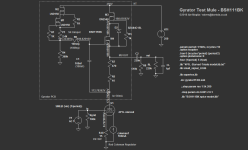
I have built the attached circuit posted in #1298 on a Rev. 0.5 board. Orientation of the BSH111 is correct and I included a 1k gate stopper on the BSH111. It works nicely with a 22k load and setting the 130V output voltage I want to use it with is no problem. When I change the load R to 8k6 to get closer to my use case (130V 15mA) output voltage drops to 54V and turning the trimmer doesn't do much. Cranking up the input voltage doesn't help.
Does anyone have a suggestion what to look for to make this work? Thank you very much.
Attachments
- Home
- Amplifiers
- Tubes / Valves
- 4P1L DHT Line Stage