The power tx is 240vac like mine?
I simulated this PSU for you.
150VDC-200VDC 30mA as per build instructions, also can design with more VDC but increase ripple.
Nope. you need 250V at the gyrator input, 215-220V minimum. Check diagram, mu gyrator output is 180V-ish and anode is 170V, so you can't aim for 150V.
AS per my email, you better stick to a proven PSU design rather than building one from scratch unless you know well what you're doing in my opinion
Ale
Thanks for support guys.
@Bela local store don't have Hammond 157M but have 158M 10H -100 mA DC - 262 ohms - 400 VDC, I guess could use it, right?
@Bela local store don't have Hammond 157M but have 158M 10H -100 mA DC - 262 ohms - 400 VDC, I guess could use it, right?
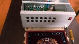
Here is my version of fully balanced differential LTP version of 4P1L preamp. Heaters are isolately powered from 250khz resonant drive along with CCS+Gyrator combination and the tubes are loaded with gyrators. +B supply turns on after 60s of heater voltage activation.🙂
Attachments
Very nice. I plan to give this a try with transformer loading. How do you like the sound?
Very well balanced, detailed and transparent 🙂
PCB
Hi Workhorse,
I presume you designed the Kanwar PCB.
Would you be willing to share it's details and design?
thanks
best regards
tim
Hi Workhorse,
I presume you designed the Kanwar PCB.
Would you be willing to share it's details and design?
thanks
best regards
tim
Hi Workhorse,
I presume you designed the Kanwar PCB.
Would you be willing to share it's details and design?
thanks
best regards
tim
Hi Tim
Yes its my design but cannot divulge its design at this moment.🙂
Though I can share some of its detailed aspect:
1 Planar transformer is used to generate 180V B+ and 4 isolated 7V heater windings.
2 All diodes in rectification are schottkys.
3 Heaters are current regulated.
4 Plate is loaded with mosfet based gyrator.
5 Cathode current is also current regulated and is fixed at 40mA
6 Planar transformer is being driven in resonant topology @ 250khz with softstart sequence
7 Differential gain setting is AC coupled.
8 The operating point being current regulated will allow the use of unmatched tubes, thanks to automatic CCS bias correction
9 Its a fully differential input and output design, even if your source is single ended, this preamp will give you differential signal output
Thanks
8 The operating point being current regulated will allow the use of unmatched tubes, thanks to automatic CCS bias correction
Really? A gyrator is a V-CCS and fixes voltage operating point, not current.
Really? A gyrator is a V-CCS and fixes voltage operating point, not current.
Who told you that I am using a Gyrator to fix current related operating point ??😕 Or had I written anywhere like that ?
Gyrator is used at plate side which fixes voltage operating point not current, Whereas CCS is used at cathode/filament side and is biased at 40mA.🙂 🙄
And each tube has its own separate CCS for biasing the operating current.
Last edited:
^CCS is also used as a plate load, where its high impedance, maximized gain of the tbe....
whereas using a resistor plate load, you can not make it very high(for large gains)
without correspondingly high plate supply B+. not so with a CCS.....
anyway, glad to see you working tubes....a different ballgame.....😀
whereas using a resistor plate load, you can not make it very high(for large gains)
without correspondingly high plate supply B+. not so with a CCS.....
anyway, glad to see you working tubes....a different ballgame.....😀
Who told you that I am using a Gyrator to fix current related operating point ??😕 Or had I written anywhere like that ?
Gyrator is used at plate side which fixes voltage operating point not current, Whereas CCS is used at cathode/filament side and is biased at 40mA.🙂 🙄
And each tube has its own separate CCS for biasing the operating current.
Misread your description above. Yes, I tried diff 4P1L with gyrator load and tail CCS long time ago as well. I liked the sound, but I don't have a differential system and prefer the single ended version. Just personal taste. Nice job btw.
anyway, glad to see you working tubes....a different ballgame.....😀
Yes, a DHT cathode follower is next on the mind for active tube XO
Nice job btw.
I also like your work with DHT's, quite inspiring 🙂
Thanks
Last edited:
Yes, a DHT cathode follower is next on the mind for active tube XO
I also like your work with DHT's, quite inspiring 🙂
Thanks
FWIW, desiderata for cathode followers is high mu. high transconductance types...
DHT's are good for gain stages...
- Home
- Amplifiers
- Tubes / Valves
- 4P1L DHT Line Stage


