I will look for it. Ping me an email please so I don't forget...
Ale
I have send you my email as PM...
/Thanks Michael.
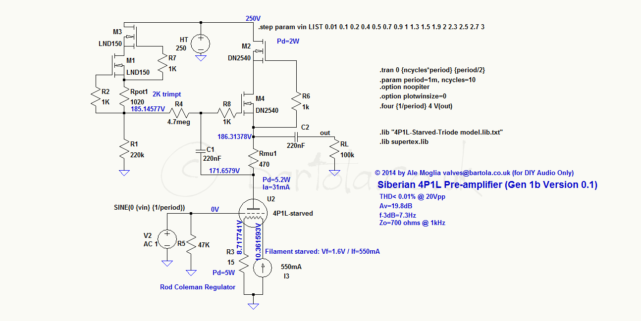
Another 4p1l line stage is born...
I have finished it and sound really really good. Its dead quiet!
I dont use any resistor at grid positions at all. No oscillation detected!
When I get the time to take some pictures I will post them.
Its a two chassis construction using tube regulation and rods filament supply.
The output transformers I used are lundahl LL1671. I must admit that they are great match!
I have build a few DHT line stages, like the 26, 01 and 1H4 and can say the 4p1l is in the same league only different...I hear more details, more colors from the best recordings. There is also a drawback all bad recordings suck! This wasnt so evident whit 26 tube. The 01 tube is also very special compared to 4p1l. I would say it has an inner spirit world. The russian girl is more conserve but plays the music most realistic way...There was no magic at first side but after a few moments it gets to you deeply...
Another 4p1l line stage is born...
Congratulations! Do post the pictures when you can. It's interesting to see how different builders manage the layout solution. You can see my next generation trial layout here: K&K Audio | Single-Ended Line Stage Preamps. It's not the last try, I suspect.
It is a very musically involving tube when you get it adjusted right and paired with the correct sort of transformer.
Hi Ale.
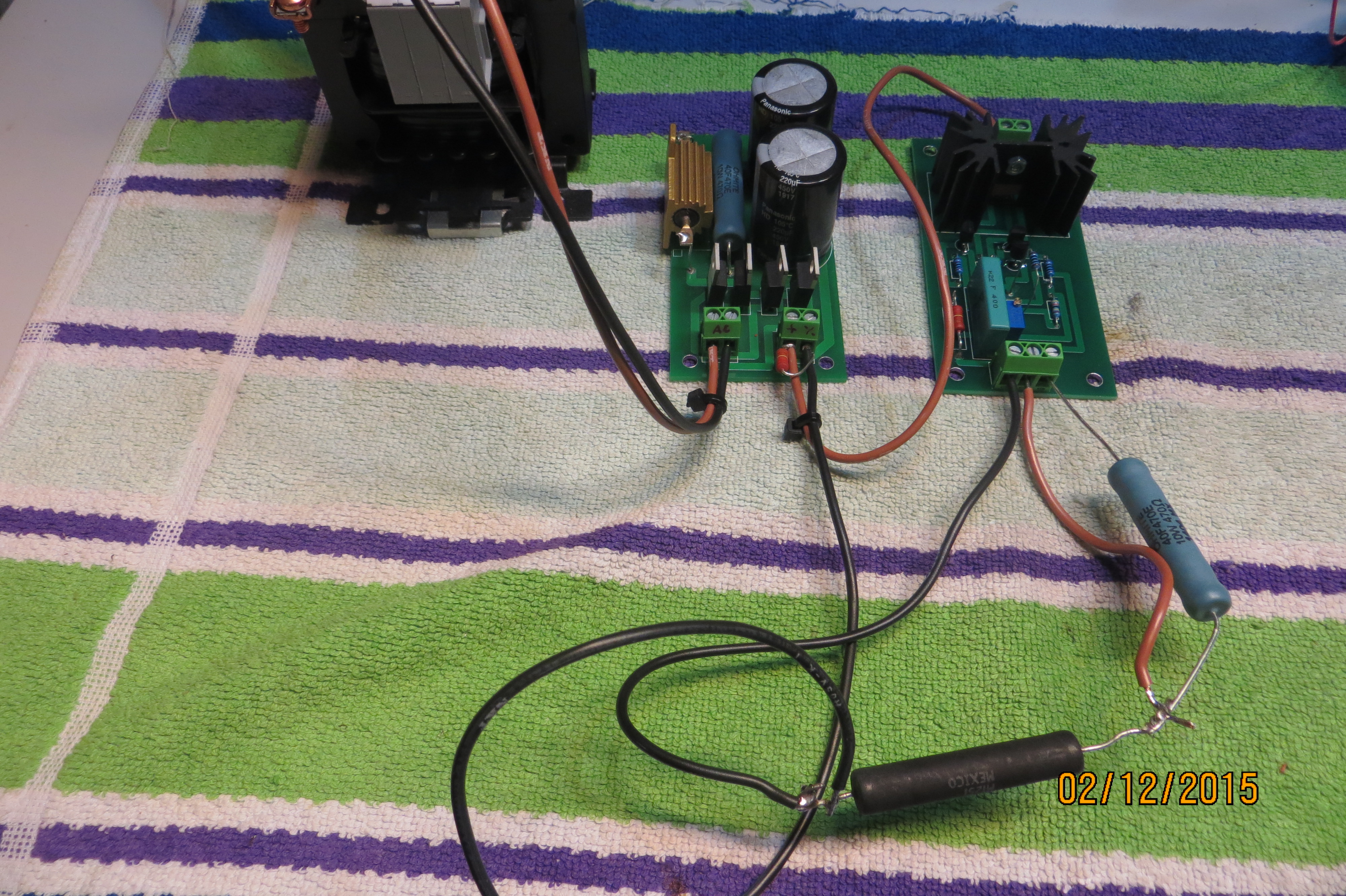
Had received my PCB today, build your Gen 1b , but with no luck.
Bjarne have done it 2 weeks ago he has the same result.
The gyrator is not regulating, I got the nearly the same voltage out on Rmu1 as
I have on my B+.
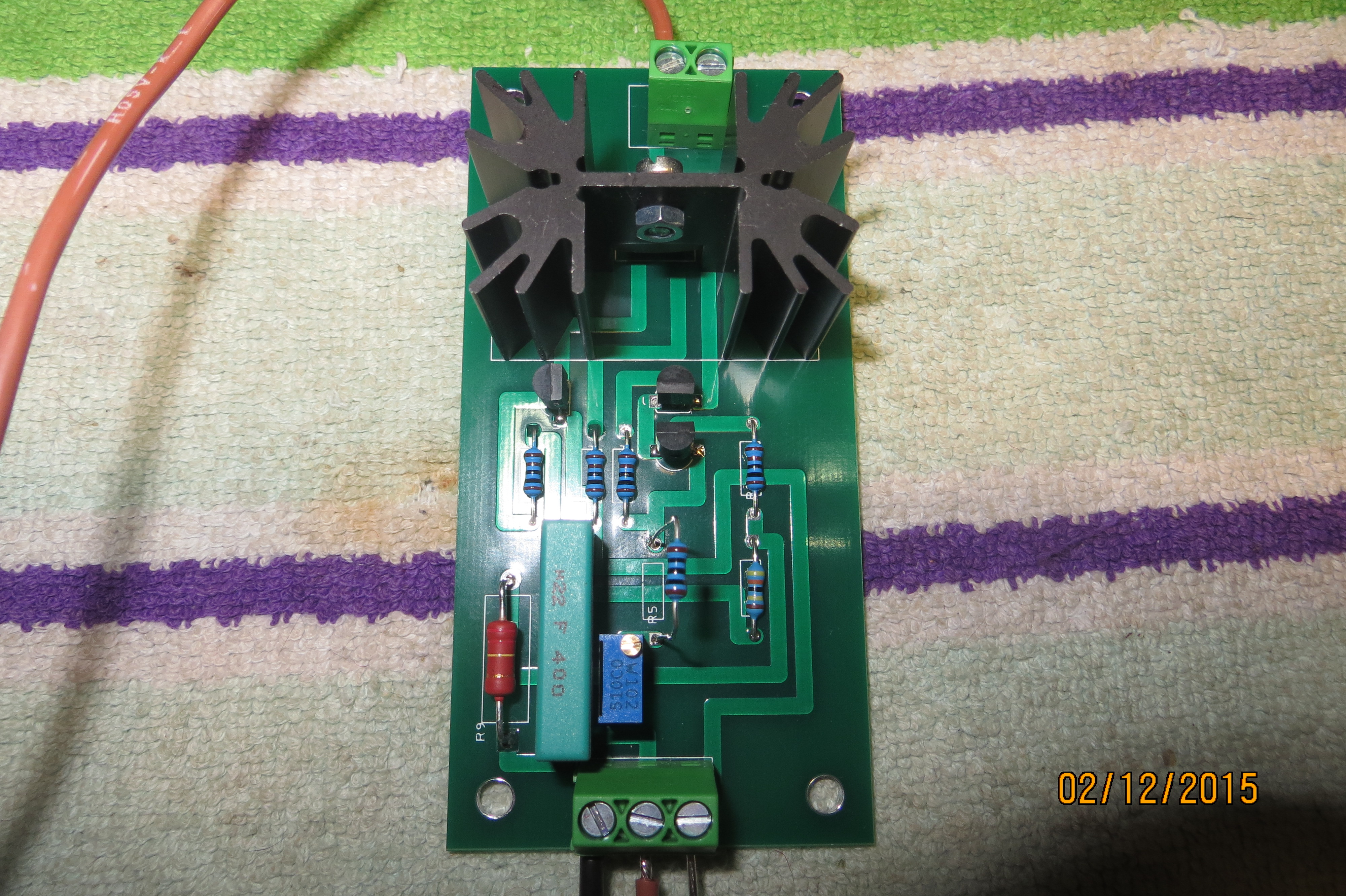
Picture of my PCB.
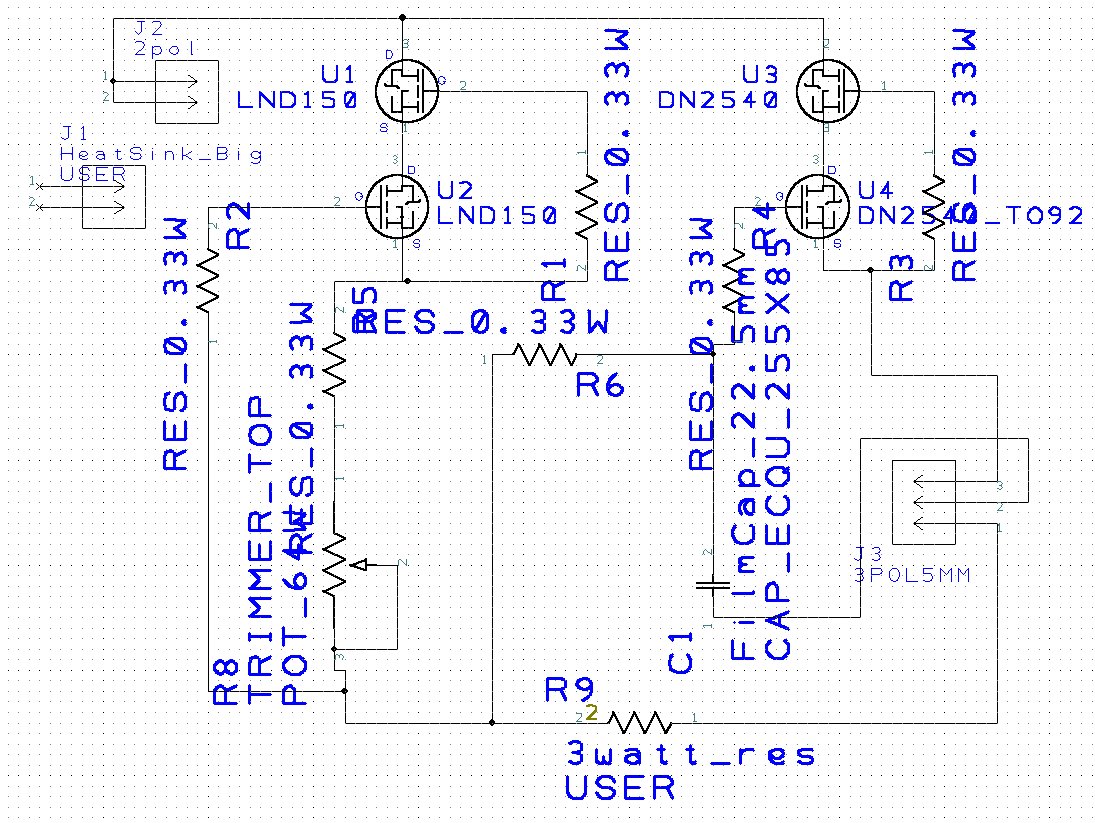
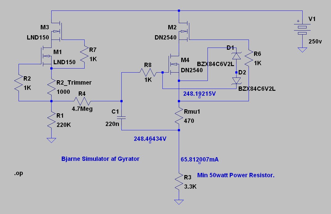
Schematic in DesignSpark.
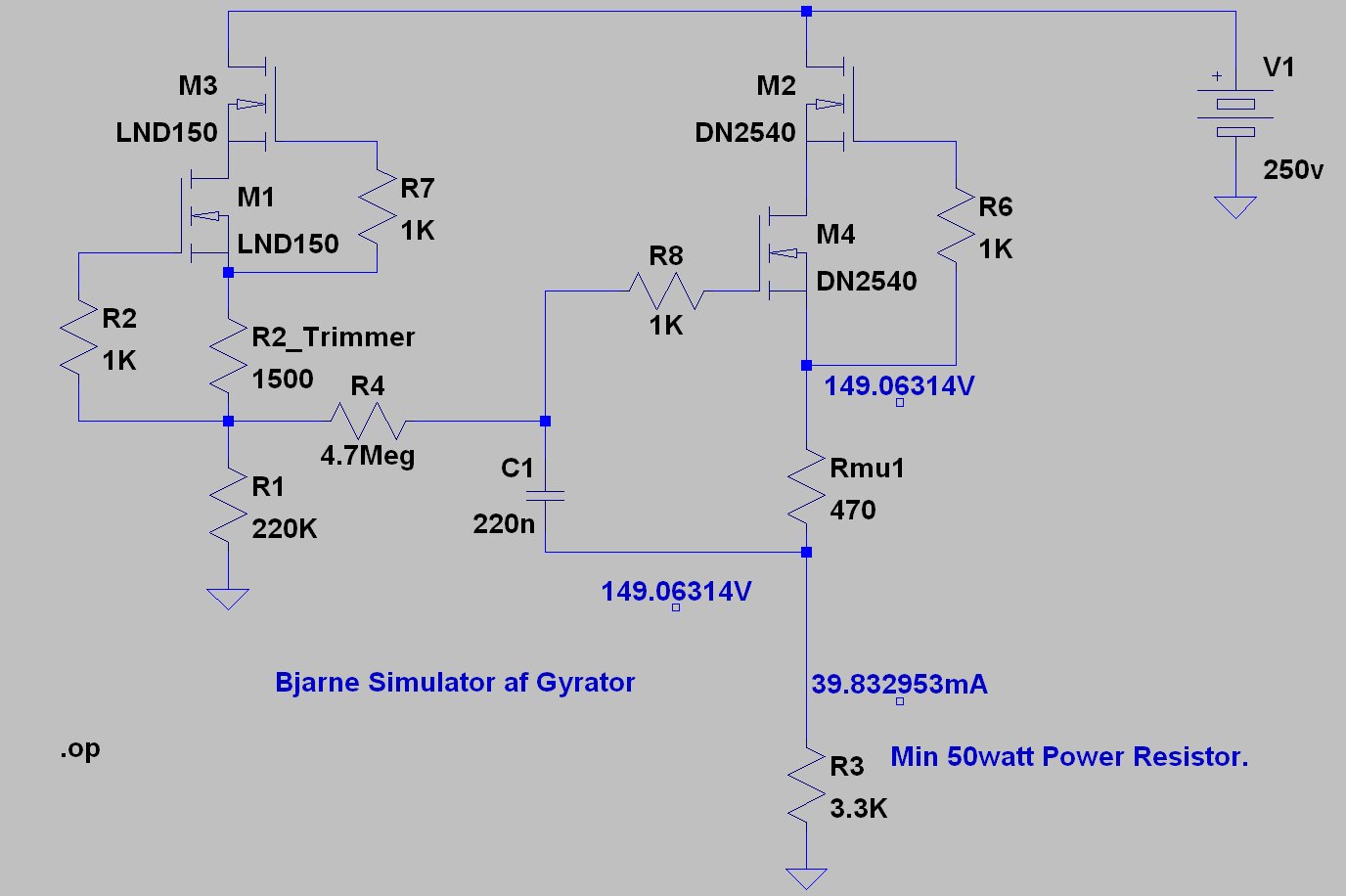
Simulation over Resistor 3.3K Looks fine.
PS! Works fine in LT-Spice. I'm confused.
/Michael
Had received my PCB today, build your Gen 1b , but with no luck.
Bjarne have done it 2 weeks ago he has the same result.
The gyrator is not regulating, I got the nearly the same voltage out on Rmu1 as
I have on my B+.
Picture of my PCB.
Schematic in DesignSpark.
Simulation over Resistor 3.3K Looks fine.
PS! Works fine in LT-Spice. I'm confused.
/Michael
Last edited:
Another 4p1l line stage is born...
I have finished it and sound really really good. Its dead quiet!
I dont use any resistor at grid positions at all. No oscillation detected!
When I get the time to take some pictures I will post them.
Its a two chassis construction using tube regulation and rods filament supply.
The output transformers I used are lundahl LL1671. I must admit that they are great match!
I have build a few DHT line stages, like the 26, 01 and 1H4 and can say the 4p1l is in the same league only different...I hear more details, more colors from the best recordings. There is also a drawback all bad recordings suck! This wasnt so evident whit 26 tube. The 01 tube is also very special compared to 4p1l. I would say it has an inner spirit world. The russian girl is more conserve but plays the music most realistic way...There was no magic at first side but after a few moments it gets to you deeply...
Perhaps play with the load line/bias to bring the 2nd harmonic up a bit as low distortion is not an issue. At this point it becomes a voicing issue.
Hi Michael,
Check №1:
Where is Rmu1 (470Ω) on the PCB? I can't see it.
If Rmu1 is not on the PCB, please be careful never to apply power when the resistor is not connected, because the DN2540 FET gate will be very easily damaged (the gate voltage must not exceed the Source voltage by more than 20V, even for an instant).
Replace U4, to check.
It is much better to have Rmu1 on the board, to ensure it is connected all of the time. If you really do not want to do this, please add a 4.3-10V zener, cathode to gate, to protect it.
Check №2:
The dc readings of voltage will be wrong, if the FETs oscillate. This is possible, because the gate resistors are a little too far from the gate pins - 25mm can be too much, sometimes. Please check for oscillation, with a scope.
Looking again, the zener is needed in all cases, since the DN2540 is not used here in the normal «current throttling» mode. It is certainly in danger, in this circuit.
Best method, for protection of depletion FETs:
Connect two 4.3-10V zeners in series (anodes together) & connect to U4 gate and U4 source.
If the PCB were mine, here is how I would debug it:
1. Cut the trace to J3 pin 3, and insert the 470 Rmu1 there.
2. Short J3 2 to 3 - to provide a single connexion to the anode.
3. replace U4 - it may well be failed short.
4. Check for shorts, where possible.
5. Apply B+.
6. check that R6 has 160-190V on both sides.
7. check that the anode voltage is nearly the same as in step 6.
Hi Michael,
Check №1:
Where is Rmu1 (470Ω) on the PCB? I can't see it.
If Rmu1 is not on the PCB, please be careful never to apply power when the resistor is not connected, because the DN2540 FET gate will be very easily damaged (the gate voltage must not exceed the Source voltage by more than 20V, even for an instant).
Replace U4, to check.
It is much better to have Rmu1 on the board, to ensure it is connected all of the time. If you really do not want to do this, please add a 4.3-10V zener, cathode to gate, to protect it.
Check №2:
The dc readings of voltage will be wrong, if the FETs oscillate. This is possible, because the gate resistors are a little too far from the gate pins - 25mm can be too much, sometimes. Please check for oscillation, with a scope.
Hi Rod...
470R is connected through the terminal block pol-3.
I haven't had power on without the 470R.
Full Picture here.
/Michael.
Hi Rod...
470R is connected through the terminal block pol-3.
I haven't had power on without the 470R.
Full Picture here.
/Michael.
DN2540 U4 replaced no difference at all..
First DN2540 U3 is cold as Ice. It should reach a quite high temperature.
Something is not regulating. But why ??
PS! Tried my OLD super simple CCS 2*DN2540. Works as expected.
Looking again, the zener is needed in all cases, since the DN2540 is not used here in the normal «current throttling» mode. It is certainly in danger, in this circuit.
Best method, for protection of depletion FETs:
Connect two 4.3-10V zeners in series (anodes together) & connect to U4 gate and U4 source.
If the PCB were mine, here is how I would debug it:
1. Cut the trace to J3 pin 3, and insert the 470 Rmu1 there.
2. Short J3 2 to 3 - to provide a single connexion to the anode.
3. replace U4 - it may well be failed short.
4. Check for shorts, where possible.
5. Apply B+.
6. check that R6 has 160-190V on both sides.
7. check that the anode voltage is nearly the same as in step 6.
Thanks Rod.
Will try to make a new schematic things are getting a little complicated.
Hopefully You'll have some comment.
/Michael.
hey Michael,
What's the voltage on PCB R9, and R6
please measure both sides.
Hi Rod.
This might be usefull.
I tried to meassure the voltage over R6. It was about 150 volt for about
20 sec, then it was close to Zero.
R6 is still 220K so it's still fine.
Something is wrong for sure...
/Michael.
OK, now - Please connect the meter BLACK lead to Ground, then measure each side of R9, and R6, with the RED lead.
OK, now - Please connect the meter BLACK lead to Ground, then measure each side of R9, and R6, with the RED lead.
R9 R9-2 130 volt R9-1 0 volt GND
R6 R6-1 130 volt R6-2 213.4 volt
When I adjust the trimmer the voltage over R6 is adjusting as well.
The voltage over R6-2 is about 2 volt under the B+.
When I adjust the B+ from 210-250 volt the R9-2 is quite close to the 130-132 volt.
The expected voltage drop over U3-DRAIN to U4-source is still only a couple of volt.
Last edited:
What that tells us is that the DN2540 gate is broken. It is feeding R6 from the FET end, rather than R6 feeding the FET.
Please try fitting the zeners ( 2 in series) as described in post 988), replace U4 and re-try.
The zeners will protect the FET, which cannot work in this circuit without voltage limiting.
Please try fitting the zeners ( 2 in series) as described in post 988), replace U4 and re-try.
The zeners will protect the FET, which cannot work in this circuit without voltage limiting.
What that tells us is that the DN2540 gate is broken. It is feeding R6 from the FET end, rather than R6 feeding the FET.
Please try fitting the zeners ( 2 in series) as described in post 988), replace U4 and re-try.
The zeners will protect the FET, which cannot work in this circuit without voltage limiting.
Hi Rod...
Something like this.
This "destroys" the ability to adjust the voltage in Lt-Spice.
In this simulation I was using 6.2 volt Zener.
What to believe after all ???..
/Michael.
Yes, your 3.3K load takes so much current that in turn, makes the gate voltage too high.
Try changing the zeners to 15V type, and upping the load value to 6,8K.
Rod
Try changing the zeners to 15V type, and upping the load value to 6,8K.
Rod
Yes, your 3.3K load takes so much current that in turn, makes the gate voltage too high.
Try changing the zeners to 15V type, and upping the load value to 6,8K.
Rod
Hi Rod...
Didn't change things...
What should the desired voltage drop from DN2540 U4-gate to U2-source the one in to-92 housing be ??.
In Lt-Spice I only have ca 0.03 volt is this enought ???
The simulation is difficult to control because the DRAIN-SOURCE voltage on the bottom device - U4- is small and hard to predict, since it is contrlled by the gate-source voltage of the UPPER device.
Are you connecting a triode for a load, or 3.3K? If 3.3K beware that this means 55mA when the voltage is 180V, and 4W burn in the upper device. (hope you have a heatsink!)
TBH, it would be much easier to add the zeners, as I have suggested, and measure the results, rather than worry about the sim.
Are you connecting a triode for a load, or 3.3K? If 3.3K beware that this means 55mA when the voltage is 180V, and 4W burn in the upper device. (hope you have a heatsink!)
TBH, it would be much easier to add the zeners, as I have suggested, and measure the results, rather than worry about the sim.
- Home
- Amplifiers
- Tubes / Valves
- 4P1L DHT Line Stage