Do your grounding correctly, I think that's your problem. It amazes me though, you're running in circles, but still haven't posted one drawing of your ground connections. All it takes is a pencil and paper.
I will see if can make a drawing....but i have try 6 different grounding,,,and none have give better result
different grounding in my dac and digital filter box
different grounding in 4p1l box
later comes a drawing
different grounding in my dac and digital filter box
different grounding in 4p1l box
later comes a drawing
Isolate the problem. First make sure that the preamp alone works without hum. Plug the 4P1L preamp directly into the wall, feed it with signal from a battery powered device (e.g. ipod, portable cd player). Connect the output to a commercial power amp if you have one, that you know for sure that it has no hum at normal power levels.
I had first also only one transformer with separate winding and I had also noise on output. Then I switch to two independent transformer and the noise is gone 😉I use only one trafo for Coleman regulator...seperate windings---is this very bad ??
best bjarne
For the test you can try to put only one valve in preamp and check the noise.
Last edited:
Neskor
what version do you use..with trafo out or gyrator
i will certainly try two trafoes for Coleman,,,have tried only one tube..still noise
i think the best way is to start all over..but first i will try to compare it in another setup
because the sound is very good--i will spend all the time necessary
what version do you use..with trafo out or gyrator
i will certainly try two trafoes for Coleman,,,have tried only one tube..still noise
i think the best way is to start all over..but first i will try to compare it in another setup
because the sound is very good--i will spend all the time necessary
Currently I'm using CCS in anode and capacitor on output.Neskor
what version do you use..with trafo out or gyrator
I also tried with output transformer but third harmonic was to high.
Hi Neskor
very interesting, would you please be so kind and post a schematic of your
Preamplifier? What current and voltages and which ccs do you use?
Greetings
ulf
Currently I'm using CCS in anode and capacitor on output.
very interesting, would you please be so kind and post a schematic of your
Preamplifier? What current and voltages and which ccs do you use?
Greetings
ulf
Just standard CCS toplogy on anode:Hi Neskor
very interesting, would you please be so kind and post a schematic of your
Preamplifier? What current and voltages and which ccs do you use?
Greetings
ulf
An externally hosted image should be here but it was not working when we last tested it.
I'm using DN2540. Current is 30mA and voltage on top of CCS ia around 200V.
funny,,,Michael who use nearly same gyrator diagram..has no noise. i will hear if i can try my pre by him
what difference in sound gyrator vs trafo
I didn't have time to properly listen this new set up with CCS. Just 5 min. listen.
Very similar to transformer. You can try 😉
And you will have 8 x amplification of input signal.
After trying so many difference things to wiring,,,i will start totally from new..
So ,can anyone draw a grounding schema for me..???
found this on moglias side about 26 preamp
The most important part of the build work is grounding and avoiding ground loops. A combination of star grounding is recommended. I do the following star ground combination:
Input stage
Filament bias return
Output stage
You definitely want to avoid the filament current ground introducing hum in the output stage so you want to keep the three star ground points separate.
What does it mean to keep star ground seperate ??
Best Bjarne
Bjarne,
Use my 4P1L Line Amp basic schematic. Wire the internal grounds like this.
Connect the Ground "Star point" to chassis near the input terminals.
Don't use chassis as a "wire" to connect things together!
Try to make the input wiring very short (input socket near the volume control, and near the 4P1L socket) or used shielded internal wiring.
You must find the reason why the output trafo caused such buzzing - maybe the high voltage supply has noise......
Attachments
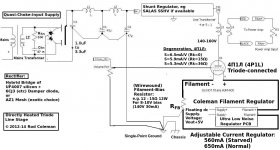
Please make the heavy black lines in the drawing (filament wiring) short, and use 1mm cable.
Please check that the Raw dc voltage to the regulators is 5V (4,5 - 7V) above the output voltage.
Typical: 15,5V in... 10V out.
Please check that the Raw dc voltage to the regulators is 5V (4,5 - 7V) above the output voltage.
Typical: 15,5V in... 10V out.
See #574 for those three points he's referring to. Did you place capacitors close to those four regulators? and is there at least 80 volts input to output difference on those maida regs?
These points return to starground:
... and of course the filament resistors go to star ground.
I guess your potmeter is at the bottom of the picture, that's a very busy position wrt radiation of rectification pulses. You could place your pot inbetween the output transformers.
These points return to starground:
An externally hosted image should be here but it was not working when we last tested it.
... and of course the filament resistors go to star ground.
I guess your potmeter is at the bottom of the picture, that's a very busy position wrt radiation of rectification pulses. You could place your pot inbetween the output transformers.
Last edited:
Thanks Rod
I will get the wire short this time,,
will order new trafo for Coleman supply
I can not messure any noise af the high volt supply...but this is not so easy to messure noise
best Bjarne
I will get the wire short this time,,
will order new trafo for Coleman supply
I can not messure any noise af the high volt supply...but this is not so easy to messure noise
best Bjarne
disco
Maida reg 275 volt in 190 out--- give me 150 volt to tube after the Lundahl
just now i have caps near regulator-- same noise..so there for i started with a new way to mount it..so i will place thinks very close together
Maida reg 275 volt in 190 out--- give me 150 volt to tube after the Lundahl
just now i have caps near regulator-- same noise..so there for i started with a new way to mount it..so i will place thinks very close together
If you replace your pot inbetween the inputs and the tube sockets the noise will probably be gone. Try without the pot if you have an adjustable output on your source.
Please check that the Raw dc voltage to the regulators is 5V (4,5 - 7V) above the output voltage. Typical: 15,5V in... 10V out.

It's just you 😀Is there other who have noise in there 4P1L...or is it just me ???
Last edited:
- Home
- Amplifiers
- Tubes / Valves
- 4P1L DHT Line Stage