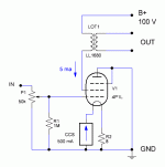
With the Rod Coleman regulators you can easily dial the current down to starve filaments at 550mA and with the silent blocks there is no issue at all with the microphonic feedback. You can get just an initial random "ding" when warming up the valves 🙂
http://www.bartola.co.uk/valves/2014/04/21/4p1l-dht-preamp-siberian-gen3-finished/
Cheers
Ale
Hi Ale...
I can have a very little, When I skip number.. But I need to play very very
loud. Plus I'm playing directly "into" my Speakers....
Again not an issue at all.
/Michael.
Hello
Like to know how the right way is to wire the volume pot
On the Gen3 is the input wire mounted to the regulator pin on the volume
i have mounted my regulator pin direkt to pin 6 on the tube
what is the right way to wire the volume ??
Why do my volume get loud when i just turn wery little on it ?
i have just make the 4P1L to play...the sound is better than i have hope for
best Bjarne
4P1L Screen Mode
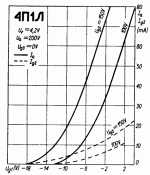
I'm waiting for my shipment. While collecting info, I stumbled upon Weird pentode connections thread that got me thinking, since the 4P1L max screen current is rated at 10mA, there is a viable option to operate it as a true triode by taking output from G2. Both G3 and Anode are grounded and act as a shield. By selecting Ig2 bias at ~5mA, we can readily use the chokes and other loads suitable for the #26. The prospect to be able to listen to a wire anode really picked my curiosity, it may share some sonic signature to the mesh plates, or even a uniquely different signature altogether. Any experience, comments or pitfalls to avoid?
I'm waiting for my shipment. While collecting info, I stumbled upon Weird pentode connections thread that got me thinking, since the 4P1L max screen current is rated at 10mA, there is a viable option to operate it as a true triode by taking output from G2. Both G3 and Anode are grounded and act as a shield. By selecting Ig2 bias at ~5mA, we can readily use the chokes and other loads suitable for the #26. The prospect to be able to listen to a wire anode really picked my curiosity, it may share some sonic signature to the mesh plates, or even a uniquely different signature altogether. Any experience, comments or pitfalls to avoid?
Attachments
That is normally done by connecting together G2 and G3 as the plate.
Here is an interesting article using the 6AU6
http://audiophool.com/Misc/6AU6 grounded plate.pdf
Here is an interesting article using the 6AU6
http://audiophool.com/Misc/6AU6 grounded plate.pdf
Hi Indra, To reduce the Anode (now - was the screen) current to 5mA, the bias probably needs to be much greater than filament bias into 8 ohm..
If you use ordinary cathode bias to see if it works properly, the job will be quick to perform, and you can re-calculate for filament bias later. If you have the trafo, why not give it a try?
If you use ordinary cathode bias to see if it works properly, the job will be quick to perform, and you can re-calculate for filament bias later. If you have the trafo, why not give it a try?
Hi JLH, thanks for the interesting article.
Hi Rod, thanks for the suggestion, you could be right. I was using this curve as a guide, but there is quite a bit of variation on Ig2 curves on several datasheets. Unfortunately I still need to wait for the shipment of the tubes to confirm.
Hi Rod, thanks for the suggestion, you could be right. I was using this curve as a guide, but there is quite a bit of variation on Ig2 curves on several datasheets. Unfortunately I still need to wait for the shipment of the tubes to confirm.
Attachments
Last edited:
Hi Indra,
Looks like a great idea to try out to me. I'm currently travelling, but when I get back home I can trace the 4P1L curves in this mode. This should help out to establish the right bias point as a starter for ten. Then you can tweak it by listening 🙂
Ale
Looks like a great idea to try out to me. I'm currently travelling, but when I get back home I can trace the 4P1L curves in this mode. This should help out to establish the right bias point as a starter for ten. Then you can tweak it by listening 🙂
Ale
Doesn't it look the like the "plate impedance" is much higher if you use the 4P1L with g2+g3 as the anode (and the actual plate grounded)?
If yes, then that would make transformer coupling more challenging, no?
--
If yes, then that would make transformer coupling more challenging, no?
--
Hi Rongon,
Yes, I expect "plate resistance" is at ~7-10k on G2 output connection with G3 grounded, should be a bit lower if output taken from G2+G3. However, many in this thread already have the transformer or choke suitable for the #26 (~8k Rp) pre amp.
Yes, I expect "plate resistance" is at ~7-10k on G2 output connection with G3 grounded, should be a bit lower if output taken from G2+G3. However, many in this thread already have the transformer or choke suitable for the #26 (~8k Rp) pre amp.
Last edited:
Hello
Need some help to reduce hum and buzzz--in my 4P1L pre
My 4p1L use Maida regulator for highvolt---Rod coleman for heater---50k volume pot---Lundahl 2745 40ma trafo for output
my version is Gen 3 Bartola
Star earth ---from volume..highvolt sekundare side...from 15ohm bias resistor
trafo is in a seperate box--together with diode and caps to highvolt
so the highvolt is 275vdc to Maida regulator
20vac to Coleman---from trafo in same box as the highvolt
150vdc from Lundahl trafo to Anode
8,7vdc over the 15ohm bias resistor
noise the same without input to volume (no influence from volume)
But still have hum and buzz...can only hear it without music---but can hear it on 3 meter from speaker---
I will try to take some picture..but need help to do that-(i will ask a friend )
best Bjarne
hi Bjarne,
Some check points:
- Signal-Chassis only connected to 0V at one place, near input-0V
- PSU cap after rectifier should not be connected to 0V directly - connect to the next PSU cap, and only then to 0V/chassis.
- Grid Wiring should be short (preferably, <100mm). If it is longer, shielded cable may help.
You can measure the ac-noise voltage with a meter, or preferably a scope. Measure filament, and the anode supply voltage for noise.
Yes, a photo will help.
Hi Rod
My signal wire from volume to tube is about 25cm long...Is that what you call grid wire ?
My star earth have no connection to chassic,,and placed around 15cm from input (only one star point )
none of my highvolt caps have connection to ground...(after rectifier- cap -resistor-cap-resistor---and then to Maida regulator..--Minus from Maida then goes to star earth
best bjarne
Hi Rod
My signal wire from volume to tube is about 25cm long...Is that what you call grid wire ?
My star earth have no connection to chassic,,and placed around 15cm from input (only one star point )
none of my highvolt caps have connection to ground...(after rectifier- cap -resistor-cap-resistor---and then to Maida regulator..--Minus from Maida then goes to star earth
best bjarne
Bjarne, yes 250mm of input cable needs to be screened - this can be enough to give humm.
Connect the screen at the input end, leave the other end unconnected.
It would be best if you draw on a piece of paper exactly all the connections, grounding, signal, etc.; take a picture with your phone and post it here. It's very difficult to know what exactly you have done and give you advice on such vague descriptions.
Iko
i have send a mail to a friend who can help me with the foto and drawing--hope later today we can post a picture
i have send a mail to a friend who can help me with the foto and drawing--hope later today we can post a picture
Hi Barjne,
As per Iko and Rod's suggestions, AC-noise/FFT measurements and a picture of the actual wiring will help here as the circuit is well known.
Just an additional suggestion: I'd also try not to ground the secondary winding and leave it floating. If your amplifier input has the ground connected to earth (hopefully at the input connection) you may experience a ground loop with the preamp. Just do this quick test to discard this potential source of hum in the 4P1L preamp
Cheers
Ale
- Home
- Amplifiers
- Tubes / Valves
- 4P1L DHT Line Stage


