Be careful when abusing such a tetrode without a forced current limit in G2.
The cathode can deliver current without end, intended to feed the plate.
If the d.c. plate voltage fails, then G2 gets it all and evaporates.
I learned that the hard way with a QQE06/40 when I still was in school.
Oh, those tears!
Gerhard DK4XP
The cathode can deliver current without end, intended to feed the plate.
If the d.c. plate voltage fails, then G2 gets it all and evaporates.
I learned that the hard way with a QQE06/40 when I still was in school.
Oh, those tears!
Gerhard DK4XP

Be careful with Ultra Linear, the screen grid voltage is very low compared to plate voltage.
However consider using the screen as plate, as mentioned earlier.
For audio you don’t want noisy fans cooling these tubes, so using the plate is probably not what you would want.
What output power would you want?
Regards, Gerrit
However consider using the screen as plate, as mentioned earlier.
For audio you don’t want noisy fans cooling these tubes, so using the plate is probably not what you would want.
What output power would you want?
Regards, Gerrit
Thank you all for this very valuable discussion!
Due to all these constraints I eventually decided to part with all these tubes (four 4XC250B's, 8438, QB2/300, four LS50's), as I'm not a radio ham (OM) and there's no sensible audio use in perspective. I'll hand over the earnings to the lady who gave them to me, widow of a German OM who sadly passed last September.
Best regards!
There have been some builds on here using GU50 which was apparently a copy of LS50, so that that one at least should have some proven designs for Audio use, and with the GU50 be abundant, replacements shouldn't be much of an issue.
Yes, absolutely true. Good for up to 120 W per pair in PP AB2. Anyway, in the last decades I've acquired a bagful of GU50's including their holders, but haven't got any LS50 holders yet, which are different. In addition, I hope some militarists may find favour in them, due to their W*******t labelling 😎. I've also got a dozen or so FL152's, another RL12P50/LS50 descendant.
Best regards!
Best regards!
Ah, brings back memories of the countless sleepless nights I spent as an undergrad studying the design of an Amplifier Research distributed amplifier, had about a dozen 4CX250Bs in it. If I had known about LDMOS transistors, I probably wouldn't have wasted so much time trying to built one using BJTs😆
These things are almost the worst possible tube you could use for audio. First, you MUST blow a massive amount of air through the sockets just to light the filaments up. If you don't, you will have issues with the ceramic to metal seals. Second, these are VHF/UHF power tubes. If you aren't extremely careful, you'll make a 150 MHz oscillator. That's what it was born to do, and it's going to try it's hardest to do so. On the flip side, a pair of these, some copper tubing and two air or vacuum caps and you've got yourself a very nice ~500W push-pull VHF oscillator.
Some RF tubes work well in audio service. These aren't one of them.
Здесь уже были некоторые сборки с использованием GU50, который, по-видимому, был копией LS50, так что, по крайней мере, у него должны быть проверены конструкции для использования в аудиотехнике, а поскольку GU50 широко распространен, замена не должна стать большой проблемой.
Attachments
These things are almost the worst possible tube you could use for audio
vice versa
A similar tube, the 4CX150 uses a Glass insulator instead of the Ceramic insulator of the 4CX250.
Does anybody know if you can see the filament glow through the 4CX150 glass?
You should be able to make the 4CX150 work at lower voltage, but only at low power.
Just ground the plate, and use the Screen as if it was a 12 Watt dissipation Plate.
45, 10Y, etc. try the 4CX150 Screen
I once did that with a 4-65A Screen. I grounded the plate cap.
GU50s make very nice audio tubes. I wouldn't hesitate to build an audio amplifier around them, but they have very little in common with the 4CX250s...
The 4X150 is very similar to the 4CX250. I don't know if you can see the glow or not, but I do know that it MUST have forced-air chimney cooling just to light the filament up, otherwise you'll cook the socket and the glass to metal seals.
The 4X150 is very similar to the 4CX250. I don't know if you can see the glow or not, but I do know that it MUST have forced-air chimney cooling just to light the filament up, otherwise you'll cook the socket and the glass to metal seals.
I worked with 4X150s in the AN/TRC24s, but they lived inside of a metal tube IIRC, so we're visible. Didn't have much glass, so not a showboat.
All good fortune,
Chris
All good fortune,
Chris
As I said before: Not economical! 15.6 W of heater power @ 4CX250B vs. just 12 W dissipation and the limitation of triode operation don't make any sense at all, and that with a rather ugly tube that even doesn't look like one. Under these circumstances I'd really prefer 6BQ5's, 6CW5's and 6V6's, just to name some few.You should be able to make the 4CX150 work at lower voltage, but only at low power.
Just ground the plate, and use the Screen as if it was a 12 Watt dissipation Plate.
My audio ambitions with those 4CX250B got cancelled eventually.
Best regards!
You can make a good case for not using a lot of valves, just to preserve them as replacements for vintage equipment that needs them. Stuff like nuvistors, 7360s, forced air transmitting valves, the specialty valves used in microphones, etc. Lots of wonderful valves are still available cheap and cheerful (and very high performance), the Magnificent TV Tubes for example, that are "ecologically sound" in our modern diyAudio community. We can easily afford to preserve a few never-to-be-replaced types for later generations. Everybody sing along...
All good fortune,
Chris
All good fortune,
Chris
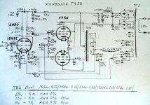
The 4CX250 was also used for Modulation purposes. Decades ago i saw a datasheet/application-note of a 600W Audio-amplifier with 2 tubes.
The attached datasheet mentions this kind of use. You can try it, but i think the costs of the output transformer will ruin your plans.😉
Good luck
Onra
The attached datasheet mentions this kind of use. You can try it, but i think the costs of the output transformer will ruin your plans.😉
Good luck
Onra
Attachments
You can see a little glow from the bottom of a 4x150. You may want to make a custom socket out of flying pins in order to see the glow. Best option would be to have the tube upside down with the flat part of the anode sitting on something like a CPU heatsink. You should be able to reduce the required airflow a bit with extra heatsinking as long as it is insulated from external contact.
At one point I ran the 4x150 up to 900 volts in triode tests and saw the distance between 10 volt grid divisions was fairly well spaced. I lost the paper scribbles of my plot somewhere though.
If you look at the earlier post of mine, you may notice you could replace an 845 with a 4x150 in some cases.
I've used many many of these, and worked with all kinds of gear that used them. I'd like to share comments on the 4CX250, 4X250, 4X150, and the B/C/F variants, and the 300 and 350 watt versions, and otherwide the whole family which plugs into that socket:
Forced air is required to cool the whole tube, even if only the heater is ON. The airflow is up through the socket and up through the anode. A chimney is required to force the air against and past the base, past the G2 ring seal, and through the anode radiator.
Some EIMAC Data sheets say so, and some say the opposite, that these can run with out the blower, with only the heater on.
EIMAC's word on it:
Must apply blower with heater: https://frank.pocnet.net/sheets/140/8/8172.pdf
For long life, apply blower with heater: https://frank.pocnet.net/sheets/140/8/8296.pdf
Don't have to run fan when heater is on:https://frank.pocnet.net/sheets/088/4/4X250F.pdf
The underside of the base requires to be in the forced air stream because the heat from the heater will overheat the base otherwise, even with no cathode-anode current flow.
The proper socket must be used, which allows air to hit the entire bottom durface of the tube, so the base can be properly cooled.
Look at the SK-600 socket to see the kind of open construction required for cooling. It is alost exactly a loktal socket, but with extreme airflow and insulation/dielectric for VHF and UHF. Just pick a socket which will flow air the same way. Avoid solid or obstructing sockets.
BTW the socket RF Parts is selling, as 4CX250B socket, is not suitable for airflow. Shame on them. Tube Depot sells it as a ceramic loktal socket, which is exactly what it is.
Aditionally to pin 1, the ring around the tube, just under the anode, is the screen grid contact when used for RF.
The slightest breath of electron current will vaporize the control grid. Well maybe not, but it has a dissipation rating of 0 or 1 Watt, depending where you do your reading, and >1mA for too long has destroyed the grids before, so be cautious. For audio, use AB1. Don't be deceived by seeing grid current in the RF specs for class C. This is intended for VHF where odd things happen, and if you push grid current into these for audio, you can very easily ruin them without warning.
They will operate on as low as 500V Plate, 350V G2, BUT this is usually done only in special work like a distributed amplifier for example there is here a Class A distributed amp making 100W from 50KHz to 225MHz. It requires 500VDC@1A split among 6 tubes. No one cares about efficiency there just bandwidth.
They will work for audio and RF at 900V on the plate but unless you want 500-600 Watts from a pair, and are willing to use 1500-2000V it's not worth it for most people to use them for audio. For 1KV anode yes they will do 200W, but so will four 811, and with much less blower noise and socket craziness.
For my part, I would not run the screens above datasheet limits (certainly not in triode mode where Eb=G2=900V) because of the very tight spacing in these tubes. In most ham gear they are run at 250-300V. Svetlava claims G2=350V on the 4CX250 and the 4X150, but I've never seen a Svet-4X150. The US-made 150's yes. The rating is 300V.
Lastly, consider how OLD most of the used tubes are if that's what is being played with. maybe good maybe not.. like people, some might have become a little addled in their dotage. If one flashes over, don't worry it won't do it again.
And the heater voltage is 6.0 volts! NOT 6.3 darn it! Yes it says 6.0 V +/-10%, but that means design for 6.0, and if your line voltage happens to vary, then c'est la vie. I would think that on an amp worthy of the fiddling and exopense required to use 4X250Bs, that it would be trivial to arrange for 6V on the heater and not use a 6.3V winding. A resistor in the primary of the heater transformer can help.
Some people commented on it: https://www.diyaudio.com/community/threads/heater-voltage-range-hi-or-low.31770/
Do as the datasheet says. It was already posted above.
RCA version https://frank.pocnet.net/sheets/049/7/7203.pdf
True some glow can be seen on the 4X150. Also, on the 4X250 - the non-ceramic version. There's a glass instead. You have to peek in to see the best glow, but WTH these can be mounted in any position.
Last edited:
Use a 6.0V power supply and measure the filament current.
0.3V / filament current = A resistor in series, from 6.3V filament windings so that the filament voltage is 6.0 Volts.
Was that difficult to figure out?
0.3V / filament current = A resistor in series, from 6.3V filament windings so that the filament voltage is 6.0 Volts.
Was that difficult to figure out?
It's preferable to measure the voltage at the tube socket and adjust the series resistor to give the desired voltage at the target mains voltage. Heater Voltage is the primary heater specification on this tube. Heater current seems uniform among specimens but why not do it right.
- Home
- Amplifiers
- Tubes / Valves
- 4CX250B - any use for them?