Hello!
I want to build a simple 4ch piezo buffer based on these JFET designs:

The plan is to feed each transducer directly into his own buffer, then put trimpots on each channel and feed them with summing resistors into a final masterbuffer.
My questions are:
1) Does passive summing of the buffered signals work as easy as that or do I need opamps etc?
2) Do I need to match the JFETs?
I want to build a simple 4ch piezo buffer based on these JFET designs:
The plan is to feed each transducer directly into his own buffer, then put trimpots on each channel and feed them with summing resistors into a final masterbuffer.
My questions are:
1) Does passive summing of the buffered signals work as easy as that or do I need opamps etc?
2) Do I need to match the JFETs?
It would help to see actual circuit diagrams rather than board layouts but from what I see the FET circuits look OK to increase the 1 meg to essentially as high as you want. 10meg is the highest common value,
The TL071 opamp can also do the same although I can't easily make out all the details easily. The same rules apply though and it quite happy with higher value resistors. The actual circuit diagrams would help a lot.
The TL071 opamp can also do the same although I can't easily make out all the details easily. The same rules apply though and it quite happy with higher value resistors. The actual circuit diagrams would help a lot.
And as to matching the FET's, no you don't need do that.
Summing using a virtual ground configuration with an opamp is the best method.
Summing using a virtual ground configuration with an opamp is the best method.
Thanks for the information!
I currently only have the JFETs here so if the summing can be done without an opamp, I would prefer this method.
Are there any tonal drawbacks to this approach?
I currently only have the JFETs here so if the summing can be done without an opamp, I would prefer this method.
Are there any tonal drawbacks to this approach?
Combine the summing and buffer into just one stage, the op amp will serve as both a summer and as a buffer.
https://www.electronics-tutorials.ws/opamp/opamp_4.html
https://www.electronics-tutorials.ws/opamp/opamp_4.html
Are there any tonal drawbacks to this approach?
Passive summing will have a bit of interaction between the four inputs that will vary depending on signal content and levels.
The virtual ground opamp (as in Rayma's link) has no interaction because each input works into what is effectively a node at signal ground potential. You would need to understand opamp theory to visualise what that means but is the best approach.
Remember an opamp on a single rail supply needs biasing to work correctly. Most examples assume a dual rail supply.
What exactly are the ineractions? Slight treble loss due to loading and not perfectly independent volume controls? Or even more extreme like bass loss etc.?Passive summing will have a bit of interaction between the four inputs that will vary depending on signal content and levels.
The virtual ground opamp (as in Rayma's link) has no interaction because each input works into what is effectively a node at signal ground potential. You would need to understand opamp theory to visualise what that means but is the best approach.
Remember an opamp on a single rail supply needs biasing to work correctly. Most examples assume a dual rail supply.
I would prefer discrete FETs precisely because I don't understand the workings of an opamp.
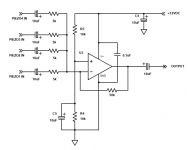
Here is a circuit to use. Duplicate the inverting input parts for each piezo buffer.
The input capacitor should be 10uF nonpolar instead of 0.1uF, though.
Use the same part for the output cap. For no gain ( 0dB ), use R1 = 5k and R2 = 5k.
Op amps are easier to use than fets, just read up on them in any text.
You will be very restricted in electronics projects if you can only use fets.
It will take just about an hour to learn all that you need to know about op amps for now.
Attachments
Last edited:
Hmm, ok thanks for the suggestion but what opamp is that circuit referencing?Here is a circuit to use. Duplicate the inverting input parts for each piezo buffer.
The input capacitor should be 10uF nonpolar instead of 0.1uF, though.
Use the same part for the output cap. For no gain ( 0dB ), use R1 = 5k and R2 = 5k.
Op amps are easier to use than fets, just read up on them in any text.
You will be very restricted in electronics projects if you can only use fets.
It will take just about an hour to learn all that you need to know about op amps for now.
Combine the summing and buffer into just one stage, the op amp will serve as both a summer and as a buffer.
Do you mean for each piezo transducer? Or do you propose using separate buffers for each piezo transducer followed by one summing amplifier?Here is a circuit to use. Duplicate the inverting input parts for each piezo buffer.
Taking into account the capacitive source impedance of piezo transducers, I think you could combine both functions by using a charge amplifier, that is, an inverting amplifier with capacitive feedback (and a big resistor in parallel for biasing). I wouldn't know a convenient way to control the gain, though.
You could use many different op amps. For line level audio, the choice is not too critical.Hmm, ok thanks for the suggestion but what opamp is that circuit referencing?
This is a completely standard, widely used circuit.
Do not try to drive a capacitive load like that without compensation - it will be completely unstable.
Hal
Hal
Do not try to drive a capacitive load like that without compensation - it will be completely unstable.
The piezo is an input, not at the output.
Nonetheless, you will need a series resistor for reasons of stability - which is already there in your schematic of post #9. I expect you also need it when you change it into a charge amplifier by replacing R2 with a capacitor with a big resistor in parallel.
Do you mean for each piezo transducer? Or do you propose using separate buffers for each piezo transducer followed by one summing amplifier?
He wants an output buffer (see post #1), which is supplied by an op amp summing circuit anyway.
The input piezo buffer should be a separate, specialized circuit due to the high impedance.
Here is a sample op amp circuit for the piezo. Use one of these circuits for each piezo.
Feed their outputs into the summing amplifier.
https://www.richardmudhar.com/blog/piezo-contact-microphone-hi-z-amplifier-low-noise-version/
Attachments
Last edited:

Can piezos actually destroy JFETs with their output if dropped?
"which is supplied by an op amp summing circuit anyway."
Not quite. I still don't see the big problem with the JFET design, for which I already own all necessary parts.
Like I said, if the only issue is not perfectly isolated controls and slight loading effects, I will go for the JFETs.
These new circuits seem to require a lot more parts and I am not the most skilled at tight veroboard soldering.
Last edited:
- Home
- Live Sound
- Instruments and Amps
- 4ch Piezo Buffer - Do I Need to Match the JFETs?