There is a problem at circuit start when there is 60 V at the input, and 0 V at the output.
Please read up the manufacturer's literature in order to understand applications, operation and limitations.
Then you will see there is no problem.
The LM317T would only be absorbing 12 volts, so where is the problem?
...and will also kill a regular 317: it will act as a slow start, meaning the regulator will see the whole input voltage during startup.
40V abs max I/O voltage, 60V or more applied = KABOOM!
I'm not sure why we don't understand each other, because I have read almost everything about 317-type regulators.Please read up the manufacturer's literature in order to understand applications, operation and limitations.
Then you will see there is no problem.
Why not pre-regulate the LM317T. Use a simple Zener + Transistor regulator before the LM317T to reduce the voltage to just above the minimum input voltage for the IC.
Indeed, a transistor bypass design is wise in some cases, and insures things are well within the safety area.
I've implimented countless designs like that with excellent reliability and results.
40V abs max I/O voltage, 60V or more applied = KABOOM!
The internal workings of the 317 are floating from ground, and internally protected from spikes, overload, and thermal issues.
Only the TL05/6/8/9/12/etc "fixed" type regulators see full input voltage.
You don't seem to get it do you?
One last attempt:
During startup conditions, the load and its bypassing will keep the output node at ~GND.
The additional 317 bypass cap will ensure the startup OP voltage is ~0 (1.25V in fact).
But, at that time, the input voltage is already ~60V, thus the differential seen by the 317 is ~60V.
Now, you can argue about the rate of rise of input supply, try to reduce the bypass cap to just pass, etc, but that's like rearranging the deck-chairs on the Titanic: weak attempts to manage a certain disaster.
Now, I give up: I you cannot comprehend the above, there is nothing more I can do
Another solution would be to use a TL783 - see chapter 9 of the PDF file below, there are some useful examples:
http://www.ti.com/lit/ds/symlink/tl783.pdf
http://www.ti.com/lit/ds/symlink/tl783.pdf
I found this online. I breaded boarded it to see if it works and it did.
It worked up to over 300 vac on the input and regulated down from
that. I also used a 50 vac transformer and it worked down from that.
I did not use it in a circuit so I don't know how it sounds.
It worked up to over 300 vac on the input and regulated down from
that. I also used a 50 vac transformer and it worked down from that.
I did not use it in a circuit so I don't know how it sounds.
Attachments
Yes, that is one of the option I recommendedAnother solution would be to use a TL783 - see chapter 9 of the PDF file below, there are some useful examples:
http://www.ti.com/lit/ds/symlink/tl783.pdf
It is not a regulator: it is a crude voltage reducer + protection.I found this online. I breaded boarded it to see if it works and it did.
It worked up to over 300 vac on the input and regulated down from
that. I also used a 50 vac transformer and it worked down from that.
I did not use it in a circuit so I don't know how it sounds.
In addition, it will require a much higher dropout voltage than what is available here
The diodes will not protect against this condition, you would need a transil across the regulator.
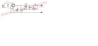
Here is an example of simple regulator, equipped with an overcurrent protection and a zener bypass:
Thanks, I will simulate it and see. The circuit seems to be good, I've just left a TIP122 left.
I found this online. I breaded boarded it to see if it works and it did.
It worked up to over 300 vac on the input and regulated down from
that. I also used a 50 vac transformer and it worked down from that.
I did not use it in a circuit so I don't know how it sounds.
If I can say, I know and tested this circuit and it is not much fine. It's useful for higher voltages and an output within 100 mA max.
Thanks, I will simulate it and see. The circuit seems to be good, I've just left a TIP122 left.
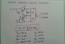
Why would you need to simulate anything? LV’s circuit is simple, almost foolproof, and easy to analyze by hand with a pencil, paper and a calculator.
And you don’t need to be limited to a TIP122. Any darlington or darlington connected pair with sufficient ratings (calculated with pencil and paper) will work.
I like this circuit a lot - I prefer something like this as opposed to using 3 terminal regulators in most applications. Especially ones where capacitive loads can risk the regulator misbehaving and blowing out a board full of IC’s that have to be replaced....
A transitorized zener regulator, simple, good...but doesn't the zd add some "noise" for the amp circuit?
So? There's always some noise. Low noise was not in the requirements. IMHO a 48V 500mA load is likely to be a High Level stage and not noise-critical. If this is really a Phantom Power supply for 48 microphones, a little filtering might be wanted, but Phantom is fairly uncritical of supply noise, and it is customary to put say 220r+220uFd on each output.
The OP requires only a 12 volt drop from 60V to a regulated 48V, so there's no problem. The LM317T would only be absorbing 12 volts, so where is the problem?
At start up. The input power goes to 60V with full force of the power company through the transformer. Any capacitor on the regulator output will start from ZERO and lag significantly behind the rise of input of raw DC. This does not always pop a '317; to puzzle the builder, sometimes it works a dozen start-ups before failing.
Also, for self-protected regulators, in overload. Load rises over 1 Amp. Regulator turns-off. Now it feels the full 60V input voltage. The cut-off breakdown may be a little higher than the 35-40V operating breakdown, but maybe 20% and not always 50% over.
I din't know how it sonds too, but I use almost the same cirquit in high-voltage (500V) component tester. All ok.I did not use it in a circuit so I don't know how it sounds.
Last edited:
- Status
- This old topic is closed. If you want to reopen this topic, contact a moderator using the "Report Post" button.
- Home
- Amplifiers
- Power Supplies
- 48 VDC from 60 V unregulated