Apologies for posting here and not on the 41hz forum - I can't seem to register there and I know folk here are pretty knowledgable.
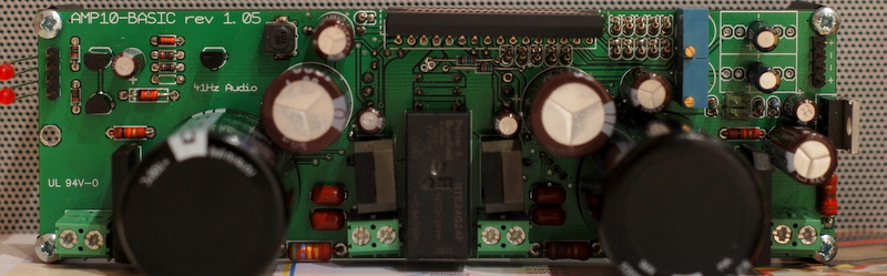
I've soldered up an amp10 - which apart from a small short in the PCB at one edge (which I've now fixed) - seems to be running, but not quite right.
My 5V+ gives exactly 5V+, my 18VAC feeds become about 2x25.5V which is right as far as I can see.
The LED which signal whether the AMP is muted or un-muted glows very dimly sometimes just after switching on or off. The other LED that shows whether the speaker-relay is open or closed seems to work perfectly. I've checked all the of the R values around the LEDs and these seem fine - though it appears the muting LED/control is driven from the Tripath chip.
The speaker terminals have a DC offset of 2.5v when measured on my autoranging meter - which is crazy high in my estimation.
No input signal or output driver is connected - and I've checked the board from shorts repeatedly!
Any ideas what could be going awry?
Cheers,
raro
short the input and try trimmer for dc offset .... max 70mv if not chip are burn , put a 1000uf to work around dc offset but......recheck all
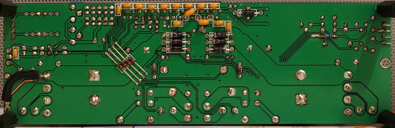
I don't have the BOM to double check but there is a resistor missing, right next to "41hz" written on the board, which I have seen fitted on another AMP10 basic.
mazdapowered said:I don't have the BOM to double check but there is a resistor missing, right next to "41hz" written on the board, which I have seen fitted on another AMP10 basic.
🙂 It's on the bottom - the holes deformed after I removed the resister for the 3rd time - took me a while to realised the BOM for Amp10 and Amp10 Basic were different.
If it wasn't there neither of the LEDs would work.
I've actually found a post on the 41hz forums that practically duplicates my issues:
http://www.41hz.com/forums/topic.asp?TOPIC_ID=1763
I think I'll give this a whirl 🙂
A bit of desoldering, the destruction of another via and a 1.5K resistor (I had no 1K) later and I'm in business - offset trimmed to a 1mV and stable. Now I just need to buy some speakers to test the amp with 😀
- Status
- Not open for further replies.