Apologies for posting here and not on the 41hz forum - I can't seem to register there and I know folk here are pretty knowledgable.
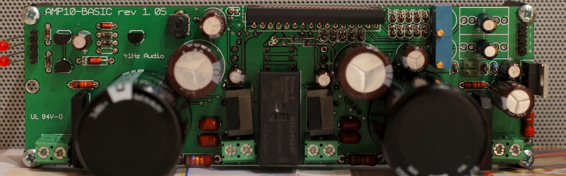
I've soldered up an amp10 - which apart from a small short in the PCB at one edge (which I've now fixed) - seems to be running, but not quite right.
My 5V+ gives exactly 5V+, my 18VAC feeds become about 2x25.5V which is right as far as I can see.
The LED which signal whether the AMP is muted or un-muted glows very dimly sometimes just after switching on or off. The other LED that shows whether the speaker-relay is open or closed seems to work perfectly. I've checked all the of the R values around the LEDs and these seem fine - though it appears the muting LED/control is driven from the Tripath chip.
The speaker terminals have a DC offset of 2.5v when measured on my autoranging meter - which is crazy high in my estimation.
No input signal or output driver is connected - and I've checked the board from shorts repeatedly!
Any ideas what could be going awry?
Cheers,
raro
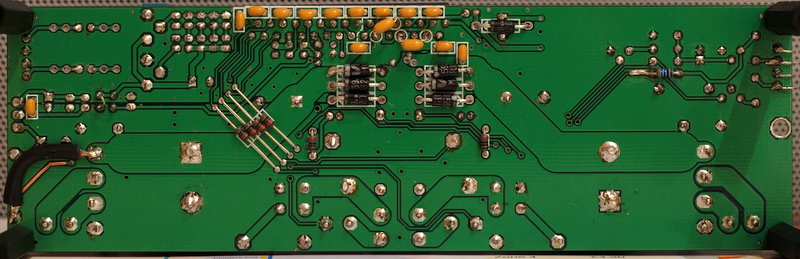
mazdapowered said:I don't have the BOM to double check but there is a resistor missing, right next to "41hz" written on the board, which I have seen fitted on another AMP10 basic.
") It's on the bottom - the holes deformed after I removed the resister for the 3rd time - took me a while to realised the BOM for Amp10 and Amp10 Basic were different.
It's on the bottom - the holes deformed after I removed the resister for the 3rd time - took me a while to realised the BOM for Amp10 and Amp10 Basic were different.If it wasn't there neither of the LEDs would work.
I've actually found a post on the 41hz forums that practically duplicates my issues:
http://www.41hz.com/forums/topic.asp?TOPIC_ID=1763
I think I'll give this a whirl
- Status
- This old topic is closed. If you want to reopen this topic, contact a moderator using the "Report Post" button.