Anyone tried the 41 Hz Amp 6? I'm torn between it and the Charlize! Any kind of comparison/info would be great.
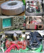
I finished the assembly of Amp 6 yesterday night. Today after a detailed visual check i fired it through a 9V AC/10W x-former. I didn't believe that it would play that good right from the start with such an inadequate power source. I listened to it for two hours. Now i left it for an extended burn-in. I will buy a 15V AC/ 80-100W x-former for this beauty. Critical listening and comments, later.
I don't have a Charlize to compare with. The Amp 6 is a good implementation of the 2020, with good quality parts and an attractive price. All that is required is a power x-former (rectifier bridge, tank cap. and regulated supply are on board), a good soldering iron with a fine tip and much attention during soldering due to very narrow pads and small inter-track distances.
Regards
George
Hi all
X-former purchased (2x15V-paralled/100VA) with very good sinusoid - not always the case with toroidals- output. Raw DC after the bridge is 21V, voltage regulator set to 13.7 V out. Amplifier gain set to X-12.
All capacitors and inductors dumped with hot silicone, also a bead placed over the edges of the PCB. The whole thing placed in a small metal enclosure (steel, except sub plate, front and rear aluminum).
Chassis connected to safety earth. PCB's ground floating. Amp is dead quiet.
On the to copper side of the 2020 chip a small 2.7mm (0.100") thick aluminum piece was attrached for increasing it's thermal mass (It didn't and it doesn't go beyond 45 D Celsius).
The voltage regulator is thermally bridged to the case (It was measuring to around 58 D Celsius, now to 45).
All in all a good package. Time to implement around 20 Hours. Price comparable to a gainclone set-up. Sound: For the time being very promising. Tests in progress.
Regards
George
Attachments
What input caps are you using on the Amp6? Most 41hz builders are reporting significant improvements with better(?) input caps, esp. compared to the 3.3uF that was supplied with the Amp3. I see that Jan is supplying FM bulk caps for some of the newer kits, and I expect they should provide a significant boost in performance.

mb
All the electrolytics (including the 3.3uF input caps) except the bulk 18000uF are FMs. I havn't substituted anything, except from one size thicker - than the supplied- wire for the output filter inductors.
Nuuk
I received the instructions as a .pdf attachment to an (automatic ) e-mail reply from 41 Hz as soon as i placed my order. If i may have your e-mail i can sent it to you.
Now, today i interrupted the burn-in for an hour and i connected the Amp 6 to the Jordans for some trials. It is still a bit stiff but i think it's getting better all the time. One thing that i am affraid won't become worse, is it's ability to expose any artifact that is present upstream, mostly in the recordings. This is just amazing.
This amp has a big mouth. Burn it in!
Regards
George
Glad to hear a few opinions on this amp... Still undecided but at least I've got a bit more info now!
Your amp looks awesome gp! Look forward to hearing more about it after it breaks in.
As for the input caps, mind if I ask a stupid question? Do they serve a purpose beyond DC blocking? In other words could you just jumper them if you were using a source or pre-amp with very low DC offset.
Your amp looks awesome gp! Look forward to hearing more about it after it breaks in.
As for the input caps, mind if I ask a stupid question? Do they serve a purpose beyond DC blocking? In other words could you just jumper them if you were using a source or pre-amp with very low DC offset.
The Tripath amps that I'm familiar with all have an input voltage bias. In the case of the Amp3 it's ~2.5 V, and I expect the Amp6 is similar.
The Tripath amps that I'm familiar with all have an input voltage bias. In the case of the Amp3 it's ~2.5 V, and I expect the Amp6 is similar.
It is, that's quite correct! 😉
mb said:The Tripath amps that I'm familiar with all have an input voltage bias. In the case of the Amp3 it's ~2.5 V, and I expect the Amp6 is similar.
That's what I was afraid of... Ah well.
For Blip 1882
Quote from Tripath’s TA 2020 Data Sheet:
“Pins 10, 13: INV1, INV2 Single-ended inputs. Inputs are a “virtual” ground of an inverting opamp with
approximately 2.4VDC bias.”
This means that a capacitor is necessary. But if your preamplifier has already one non-polarized capacitor at the output then the 3.3uf is not a neccessity.
This afternoon I asked a friend (“Fiak”) to come and listen to the Amp 6. He came bringing along his ZAPulse 2.3SE (Stereo, separate power supplies) for comparison. They do not compare in terms of available power but we gave them a go. Initial impression was that Amp 6 was more “airy”. More detailed listening clarified the “airiness” ; a bit stronger treble but most important more analytical. These micro details that a good close-mike recording can expose from the hammering of low register triple strings of a properly tuned piano were processed transparently by Amp 6, that is, the slight different pitch of each string was discernible, the thus prolonged decay was clearly outlined. ZAP was providing the resultant rich tone in a very musical way, but the ingredients were not identifiable. ZAP was controlling the bass in a better way when the power was increased. Up to 85-87 db level, the overall response (apart from the airiness given the appropriate recording) was quite equal with both amps. Above that level, Amp 6 was steaming off in complex musical passages while ZAP was retaining it’s authority. I am very pleased with the achievements of the small Amp 6. I am half deaf, but Fiak is a very critical listener and he was himself satisfied with the Amp 6. (He may post his opinion individually).
Tests started with amps driven directly from the adjustable output of the Philips CD 723. Then, they were driven by a Naim-pre copy. With the later, sound was more “bodied” but a bit less detailed.
Regards
George
Well that's a pretty resounding review for the Amp6! I'm still sitting on the fence (i'll be building it in late December so I've got a bit of time to think) but the Amp6 is looking better and better.
Just curious, do the instructions indicate the minimum and maximum input voltages (i.e. maximum and minimum voltage from the transformer secondaries). Also, do they indicate a recommended VA for the transformer?
Just curious, do the instructions indicate the minimum and maximum input voltages (i.e. maximum and minimum voltage from the transformer secondaries). Also, do they indicate a recommended VA for the transformer?
gpapag said:. But if your preamplifier has already one non-polarized capacitor at the output then the 3.3uf is not a neccessity.
It's still neccesary. To quote myself form the UK T-Amp forum.
"Even if your source has output caps you still need to block the DC. Why? Because the Tripath chip works like a DC coupled amp. If that 2.5V on the input is off even slightly, that will be amplified and find its way to your speakers.
That offset can run as high as 10V or more. Not good!
The ONLY way you could get away without the input cap would be to have a source circuit where you are absolutely sure there is no resistance or anything else across the source after the output cap, none. As you probably don't know this, use an input cap. If you really want to try it, be very sure of your source circuit and measure the DC offset of the T-amp before you hook up the speakers. You won't hurt the T- amp, but you might kill your speakers or the source. I don't recommend it."
Hi all
For blip 1882:
From TA2020 data sheet:
Absolute Max. Voltage :16Vdc
Operating Conditions:
Min: 8.5 Vdc
Typ:13.5 Vdc
Max:14.6 Vdc
Now from the data sheet of the LM 1084 (the Voltage regulator supplied with the 41 Hz Amp6):
Max In-Out Voltage Difference: 25 V dc
Drop-out Voltage: 1.3-1.5 Vdc
Summing it all up we get:
9V ac < X-Former secondary> 28V ac (Limit Values)
70 VA minimum (50W max output * 70% Efficiency=71W)
For panomaniac:
A causious remark. Thank you and my appologies to the forum. (Although i have my doupts, I will check it and report back). By the way, is it any information available for diy-ing a differential scope probe?
Regards
george
Panomaniac
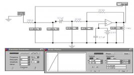
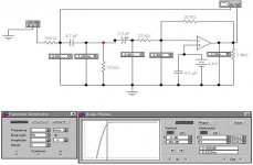
Referring to your post # 13, I didn’t do a real test yet, so your precautious recommendation is to be followed.
I did though a simulation of the input section of the TA 2020 (in my case is a 3.3uf followed by 22k feed/22kfeedback resistors into the inverting input (pins 10, 13 *). The non inverting input is tied to a 2.4VDC source to approximate it’s function (pin 14 **)
The signal source is simulated by a signal generator with or without DC offset. It’s output is modeled with or without a coupling capacitor, with or without a capacitor discharge resistor. Every screen shot -4 in total- is self explanatory. Rectangular boxes indicate DC Voltmeters.
This simulation scheme indicates the same DC offset at the Op-Amp Output, regardless of the input configuration. I would like your comments on the outcome of this simulation (or whether simulation of the real case is improperly implemented).
Quotes from TA 2020 data sheet:
*“Single-ended inputs. Inputs are a “virtual” ground of an inverting opamp with approximately 2.4VDC bias
**"Input stage bias voltage (approximately 2.4VDC)".
Regards
George
Attachments


I've constructed the AMP-6 and am about to wire it up but I have a question regarding the power supply.
I have a PSU built to provide a regulated 12 volts. This consists of a transformer with twin secondaries, supplying two LM317 regulators (ie there are two 12 volt supplies).
Is it OK to connect the two wires from the AMP-6 to one of the secondary windings of the transformer, and the ground connection to the metal case/earthwire of the PSU. Or should I disconnect the regulator circuits as well? 😕
Nuuk
If you want to test the Amp-6 "as is" and in a safe way, better disconnect the x-former secondary from your LM317 regulators and connect it only to the Amp-6 (preferably paralleling -mind the phasing of-the secondaries). Otherwise, please provide more info about your external PSUs (i.e. are they summetric +/-, or paralled, are they supply other circuit as well?)
Regards
George
- Status
- Not open for further replies.
- Home
- Amplifiers
- Class D
- 41 Hz Amp 6?