Otherwise, please provide more info about your external PSUs (i.e. are they summetric +/-, or paralled, are they supply other circuit as well?)
Thanks George. The two supplies are single rail 12 volt regulated that I have been using for the class-T's (when not using the SMPS 😉 ).
I wasn't intending on using the regulated outputs at the same time that I used the AC supply for the AMP-6 but as you say, it may be safer to disconnect them anyway.
Transformer is a 120VA, I guess that it wouldn't hurt to use both windings!
But am I correct in connecting the ground on the AMP-6 to the PSU (metal) case? 😕
Nuuk said:it may be safer to disconnect them anyway.
Probably. Better safe than...
But am I correct in connecting the ground on the AMP-6 to the PSU (metal) case?
I don't see why not. You would connect the AMP6 ground to whatever was feeding it signal, right? So why not to the case of the PSU? Unless there is something funky about that PSU ground.
I have an AMP6 running now that is not connected to ground at all. Everything in the system is 2 wire AC. CD player and transformer for the amp. No noise at all. No case on the amp, either. 😎
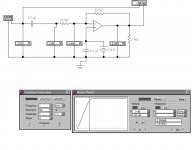
gpapag said:I did though a simulation of the input section of the TA 2020 (in my case is a 3.3uf followed by 22k feed/22kfeedback resistors into the inverting input (pins 10, 13 *)
Hey George,
I had a look at the diagrams, all looks cool. But you did not simulate removing the 3.3uF cap. That is where the trouble would come. Espesically with that 10K resistor to ground. Having done that by mistake with a 47K, I can tell you there will be a BIG DC offset.
Pull the 3.3uF out of your circuit and see what you get. Please post the results.
panomaniac said:I have an AMP6 running now that is not connected to ground at all. Everything in the system is 2 wire AC. CD player and transformer for the amp. No noise at all. No case on the amp, either. 😎
Same here, except it's an amp3 😀
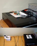
It's on top of my CD player, within a foot of my laptop using wireless internet, and three feet away from my halogen lamp and there's very little noise!
You can see the little regulator board on top of a UCD180 box and the amp on the CD player. Not exactly a noise free environment!
Attachments
One of the curious things I first noticed about the SI is that touching an input induces very little hum - a bit disconcerting!
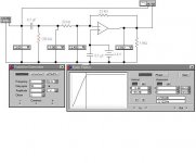
Panomaniac, you are right. I didn't simulate what i ought to. Here is the simulation with the 3.3uf removed and no discharge resistor at source output. No problem hereI had a look at the diagrams, all looks cool. But you did not simulate removing the 3.3uF cap. That is where the trouble would come. Espesically with that 10K resistor to ground. Having done that by mistake with a 47K, I can tell you there will be a BIG DC offset.
Attachments
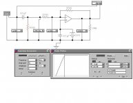
That's correct. Your red resistor is acting as a voltage divider with the 22K input R.
Any pull away from the bias will be amplified at the final output. -12X, I think. Or +12X if you are looking at the output of the opamp.
Any pull away from the bias will be amplified at the final output. -12X, I think. Or +12X if you are looking at the output of the opamp.
Right again Panomaniac. The gain formula for the TA2020 is: Vo/Vi=12(Rf/Ri). What is shown as DC offset by the rightmost voltmeter in the above simulations is only the (Rf/Ri) part. This has to be multiplied 12 times to make for the final DC offset present at the speaker terminals.Any pull away from the bias will be amplified at the final output. -12X, I think. Or +12X if you are looking at the output of the opamp.
Verdict: .Do not ommit input capacitor, or strictly follow Panomaniac instructions at post #13 in this thread.
Thanks again Panomaniac for clarifing this.
Regards
George
Nuuk
Refering to the Amp-6 ground:I have tried it both ways;isolated and connected to safety ground (chassis). When the amp has it's inputs shorted or is connected to a "2 wire" source, I can not hear any difference. No noise in both cases (this doesn't mean that they measure the same as well. I have to fix a differential probe first to test it). But if amp is connected to a "3 wire" source, then connecting or disconnecting amp ground from safety ground it may (does) induce an audible difference, depending on the grounding scheme of the source. A "ground lift" switch is helpful. (Note: I always have the third wire-safety earth- permanently attached to chassis. What the "ground lift" switch is for, is for connecting or disconnecting the amplifier's ground from the chassis on will ).
Regards
George
dnseyOne of the curious things I first noticed about the SI is that touching an input induces very little hum - a bit disconcerting!
can you please explain which is disconcerting; the hum induction itself or the"very little" part of it?

Regards
George
Hi George,
I meant that I'm used to touching amp inputs and hearing a loud hum from the output - a rough and ready check that the amp's working.
In the case of the SI, the hum was almost inaudible, and at first I thought the amp must be faulty.
Cheers,
Dave.
I meant that I'm used to touching amp inputs and hearing a loud hum from the output - a rough and ready check that the amp's working.
In the case of the SI, the hum was almost inaudible, and at first I thought the amp must be faulty.
Cheers,
Dave.
To those who have completed work on their Amp6 kit, I need a bit of help on the JP1, which has 3 holes to accept input from the secondary of the PSU. I have a center tapped 18-0-18 trafo, and my questions are as follows:
1) the rectifier used with the amp6 has 4 legs, 2 of which (the middle 2) are connected to holes 2 and 3 of JP1, then leg 1 of rectifier if connected to hole 1 of JP1, these are then connected to the (-) leg of the 16000uf cap. Is it safe to assume that I could use my center tap in hole #1 and the two 18v to holes #2 and #3?
2) Is it ok to use my 18vac trafo? I'm afraid the first filter cap (16000uf) is only rated for 25v and my 18v after rectification will be around 25.45 volts. I'm not so sure how many volts the rectifier drops.
I'm more inclined to using this 18v trafo since its rated for 6amperes. The 15v trafos available here are rated only 2amperes and the 12v trafos for 3amperes. Should I junk my 18v trafo and instead get a 12v-3amp one? Thanks for reading my post
I've got a question too! I'm only getting 0.37 volts across the 18 volt cap (with a 1 meg loading resistor).
I've checked everything in the PSU section and it seems OK. I get the expected 16.5 volts across the large reservoir cap after the rectifier (12 volt transformer).
For the voltage regulation I have used 100R and 1K with a straight wire so should be getting 13.75 volts. The datasheet for the LT1084 says it will go down to 1 volt dropout so that shouldn't be a problem. Unfortunately, I got carried away and soldered in the 2020 chip before testingthe PSU!
Could somebody with a working AMP-6 tell me what resistance they measure across the 18 volt cap (C1819)?
Nuuk said:Could somebody with a working AMP-6 tell me what resistance they measure across the 18 volt cap (C1819)?
Resistance? Do you mean voltage? I get 14.2 volts.
Resistance? Do you mean voltage? I get 14.2 volts.
No, I meant resistance. I was trying to see if there was a short somewhere after that cap.
Nuuk
I think that you have mixed R100, R101 and R102 during installation. Check if R101=1K, R100=100R, R102=0R
Regards
George
I think that you have mixed R100, R101 and R102 during installation. Check if R101=1K, R100=100R, R102=0R
Regards
George
I think that you have mixed R100, R101 and R102 during installation. Check if R101=1K, R100=100R, R102=0R
Thanks George. That was the first thing that I checked but they they are all OK. When I measure across the 1K, it measures 800 ohms. I'm not sure if that is OK or not!
D0Hbert
Ref your questions
2) With 18Vac x-former you are walking on the edge with the 25V Capacitor. It will not blow when you have 18Vac, but with line variations +10% you have 19.8 Vac, which makes 28Vdc.
1) If you have an x-former with two secondaries, you should parallel them checking the phase. Then, you have two wires for the secondary output (one the center tap and the other the two paralled ends). These two wires will be connected at #2 and #3 holes of JP1. The hole #1 is the ground (negative of rectifier bridge)
dnsey
I see. This may have to do with the input topology of the amp.
Regards
George
- Status
- Not open for further replies.
- Home
- Amplifiers
- Class D
- 41 Hz Amp 6?