I've been noodling around with HornResponse and have put together a 40hz tapped horn sub that is a single sheet design. Before I start cutting wood, I'd love to get feedback any of you might have. I mostly just want to make sure I'm not overlooking anything huge.
The main design goals:
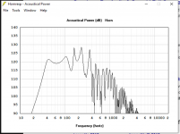
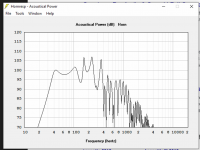
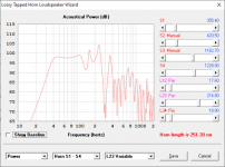
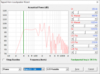
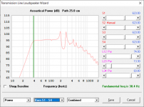
1. flat from 40hz to 110hz
2. good sensitivity, 95+ db - I'd like to be able to use in a semi portable set up using batteries and solar panels
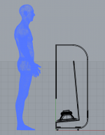
3. low overall weight - light enough to carry by one person
4. small footprint (but tall is ok)
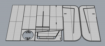
5. one sheet if possible
6. ok appearance for home use, but loud enough for small PA.
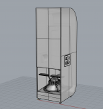
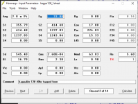
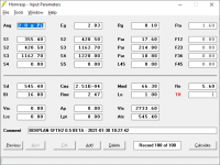
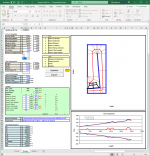
The driver I ended up with is the Kappalite 3012lf. The xmax will limit it to around 120db at 33v (I plan to use a smaller class D amp). I will build it out of 1/2" (12mm) plywood. The back panel will be made by scarfing two of the pieces together and then bent using kerfing. The weight estimate is around 50 lbs (22kg).
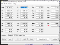
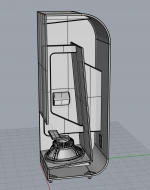
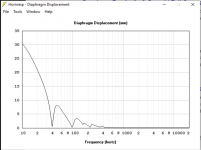
Attached here are several screencaps from HornResponse and a Rhino model along with the one sheet cut.
Thanks for your thoughts.
The main design goals:
1. flat from 40hz to 110hz
2. good sensitivity, 95+ db - I'd like to be able to use in a semi portable set up using batteries and solar panels
3. low overall weight - light enough to carry by one person
4. small footprint (but tall is ok)
5. one sheet if possible
6. ok appearance for home use, but loud enough for small PA.
The driver I ended up with is the Kappalite 3012lf. The xmax will limit it to around 120db at 33v (I plan to use a smaller class D amp). I will build it out of 1/2" (12mm) plywood. The back panel will be made by scarfing two of the pieces together and then bent using kerfing. The weight estimate is around 50 lbs (22kg).
Attached here are several screencaps from HornResponse and a Rhino model along with the one sheet cut.
Thanks for your thoughts.
Attachments
-
 Screen Shot 2021-01-28 at 9.48.10 PM.png135.4 KB · Views: 752
 -
 Screen Shot 2021-01-28 at 12.23.35 PM.png241.9 KB · Views: 458
 -
 Screen Shot 2021-01-28 at 10.49.26 AM.png173.6 KB · Views: 523
 -
 Screen Shot 2021-01-28 at 10.48.54 AM.png412.6 KB · Views: 550
 -
 Screen Shot 2021-01-28 at 10.48.09 AM.png386.5 KB · Views: 452
 -
 Screen Shot 2021-01-28 at 9.54.16 PM.png106.3 KB · Views: 722
 -
 Screen Shot 2021-01-28 at 9.54.01 PM.png133.1 KB · Views: 718
 -
 Screen Shot 2021-01-28 at 9.49.32 PM.png121.5 KB · Views: 713
 -
 Screen Shot 2021-01-28 at 9.48.28 PM.png144.7 KB · Views: 710
Looks nice. Did you check out this thread?
Single sheet TH challenge
You might want to double up on the speaker baffle if your cutting from 1/2”.
Single sheet TH challenge
You might want to double up on the speaker baffle if your cutting from 1/2”.
For sure I've read that thread - legendary 🙂
While I like the ss15, I wanted something a little lower with a different form factor. That requires giving up some efficiency, but I'm ok with the trade off.
While I like the ss15, I wanted something a little lower with a different form factor. That requires giving up some efficiency, but I'm ok with the trade off.
My POC3 is about that size and has an Fb around 40 Hz. Of course it was built back at a time when a simpler TH model was used. It can probably be improved if we apply what's been learned since then, i.e. the impact of the slug of air in front of the cone and the impact of semi-inductance on the response at the upper end of the passband.
The Subwoofer DIY Page v1.1 - Projects : "Proof of Concept #3"
The Subwoofer DIY Page v1.1 - Projects : "Proof of Concept #3"
Nice - @ 50lb, one could avoid painful hernia plus that's a great form to pack side by side..
An updated POC3 would be interesting.
An updated POC3 would be interesting.
That's very cool design. 12 mm plywood is not very stiff, but I see the braces you made. Very efficient use if material.
Brian - can you elaborate more on the lessons learned? Or could you point me any resources for the two areas for improvement you mention? Many thanks.
Some of the things I learned:
1. Take the effect of losses into consideration (use filling = 1 or 2 in each segment to emulate the effect of losses
2. Derive the semi-inductance parameters for the driver and use them in the sim. Sometimes they will make a big difference, sometimes they won't. Only one way to find out..
3. Don't bother with nice curvy bands for bass horns. All they do is consume volume which in turn reduces efficiency at low frequencies
4. Always check to see if the net volume of the box is more than the net volume indicated in the sim. If the sim's net volume is larger, then the sim is incorrect. It should be the same or smaller (via a small amount, caused by excess volume in the bends)
5. Always include the impact of the air contained by the driver's cone and the cutout on the baffle in the sim. This can be emulated by setting Vtc to this combined volume and Atc to the driver's Sd.
6. If building with 0.5" ply, consider using quarter-round molding or something similar to increase the surface area around the joints for gluing purposes. Thinner panels = less surface area for glue = more likely to separate.
7. Bracing is important! Cross-bracing from the centers of each panel is the most effective,
8. Consider doubling up on the driver's baffle. Not only for additional strength, but the screws will be less likely to come loose if they're driven into a thicker panel.
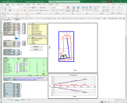
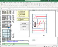
BTW, what are the external dimensions of your planned build? I tried to come up with something similar using a BOXPLAN workbook and it suggests that external dimensions of 48x14x22.5 would be required, and even then the mouth is slightly smaller than what's portrayed in your sim...
Attachments

Brian, thanks for the all the info - some fun homework for me 🙂
The external dimensions are 15" (38.1cm) wide x 18.6" (47.4cm) deep x 48" (121.9cm) tall, so a total of 13392 cubic inches, compared to your sim's 15120.
The external dimensions are 15" (38.1cm) wide x 18.6" (47.4cm) deep x 48" (121.9cm) tall, so a total of 13392 cubic inches, compared to your sim's 15120.
Actually, the volume is a bit lower because of the curved parts on the back (that Brian recommended against): 13120.5 cubic inches (215006.9 cubic cm)...
MBlanco,The external dimensions are 15" (38.1cm) wide x 18.6" (47.4cm) deep x 48" (121.9cm) tall, so a total of 13392 cubic inches, compared to your sim's 15120.
Designing speaker cabinets to fit truck dimensions makes for easier transport, most rental trucks have a bit over 90 inches in width and height.
Using the nearest box integer sizes, your sub could be made 15" wide x 24" deep x 45" tall with similar internal volume, and still work well for efficient plywood lay-outs.
Using 45 degree angles plates on the top and bottom back rear horn bends would allow wheels and bar handles to be fitted, the cabinet could be tilted back and wheeled like a two-wheel dolly.
Art
Brian, thanks for the all the info - some fun homework for me 🙂
The external dimensions are 15" (38.1cm) wide x 18.6" (47.4cm) deep x 48" (121.9cm) tall, so a total of 13392 cubic inches, compared to your sim's 15120.
With those dimensions, if I start off with the same S1 as your sim, I'm not ending up with the same mouth size. Also, the driver is not quite fitting on the baffle. Check the expansion profile of your horn as described in your chosen layout. It might not be parabolic.
Attachments

Using the nearest box integer sizes, your sub could be made 15" wide x 24" deep x 45" tall with similar internal volume, and still work well for efficient plywood lay-outs.
Because of the simple fold of this horn, that results in a path that does not tune low enough, and the box also ends up being a little too large for the driver.
Meant to write 15" wide x 22.5" deep x 45" tall, 24" is not a 90" box integer..
I'd think the reduction of height by 3" and the increase from 18.8" to 22.5" would result in the almost the same path length, and the extra .95 cubic foot box size would be reduced by the 45 degree angles plates on the top and bottom back rear horn bends that could allow wheels and bar handles to be fitted.
I'd think the reduction of height by 3" and the increase from 18.8" to 22.5" would result in the almost the same path length, and the extra .95 cubic foot box size would be reduced by the 45 degree angles plates on the top and bottom back rear horn bends that could allow wheels and bar handles to be fitted.
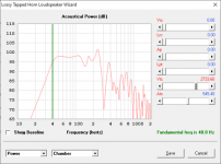
That doesn't look to bad, particularly if path is lined / stuffed a bit to address the underdamped response of the 3012LF in such a "large" TH (it would be happier in a slightly smaller volume), and if done right the lining /stuffing will drop Fb to 40 Hz. too. Some cone compensation @S2 should smooth out that little dip at the upper end of the passband if that's desired.
FWIW, I think this should be compared against using the same driver in a simple 40 Hz offset TL. There will be a few dB of output lost in the process, but the box should be smaller (like quite a bit smaller), and it will have a wider usable passband.
FWIW, I think this should be compared against using the same driver in a simple 40 Hz offset TL. There will be a few dB of output lost in the process, but the box should be smaller (like quite a bit smaller), and it will have a wider usable passband.
Attachments
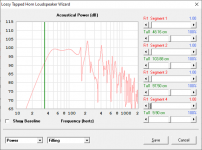
Another interesting possibility - a modified "Type C" Paraflex alignment. Same box size. Lower Fb, but more sensitive in the passband (according to Hornresp).
Note: The positioning of the driver in the rear chamber is not accurately described in Hornresp, so the response above 100 Hz might be a bit different to what is pictured.
Note: The positioning of the driver in the rear chamber is not accurately described in Hornresp, so the response above 100 Hz might be a bit different to what is pictured.
Attachments

Offset TL, 38 Hz tuning. Noticeably smaller box and wider usable passband, but you do lose a few dB of passband output. FWIW, I wouldn't build this one with 0.5" panels. I'd probably go for 0.75" for the front, top, rear and bottom panels. I'd also inset the front panel, so the external box dimensions will end up slightly larger.
Attachments
- Home
- Loudspeakers
- Subwoofers
- 40hz Single Sheet Tapped Horn