Ok - I've done some homework and updates, mostly following the suggestions from Brian in post #8. This post is still using my original outside dimensions and design:
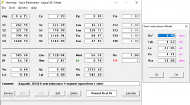
- I've added the semi inductance params to the horn response sim, it flattens the response
- I've added vtc and atc as suggested
- I've recalculated all the areas and the segment lengths, I think my first sim incorrectly had the overall length about 10cm too long (260cm, but it should be 250cm)
- I changed it to a 4 segment sim, instead of 3 segments - to capture that only the 3rd segment is Par and the others are Con
- the volume now seems to be ok, the sim volume is 182 liters, and the net volume from my rhino model is 184.1 liters
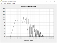
With these corrections, its apparent that its not really a 40hz sub, but maybe a 45hz sub - which is still pretty good I think 🙂. Getting to 40 will take two subs I guess...
- I've added the semi inductance params to the horn response sim, it flattens the response
- I've added vtc and atc as suggested
- I've recalculated all the areas and the segment lengths, I think my first sim incorrectly had the overall length about 10cm too long (260cm, but it should be 250cm)
- I changed it to a 4 segment sim, instead of 3 segments - to capture that only the 3rd segment is Par and the others are Con
- the volume now seems to be ok, the sim volume is 182 liters, and the net volume from my rhino model is 184.1 liters
With these corrections, its apparent that its not really a 40hz sub, but maybe a 45hz sub - which is still pretty good I think 🙂. Getting to 40 will take two subs I guess...
Attachments

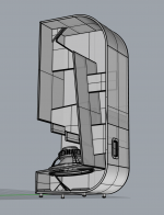
I've redone this design again with two things in mind:
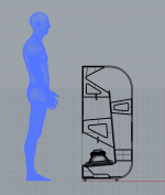
- reduce the physical width as much as possible just allowing enough room for the driver, the overall cabinet width is now 13.5" (34.15cm)
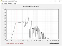
- and adjusting the other dimensions to get flat response back down to 40hz
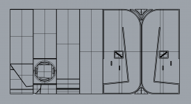
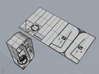
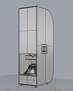
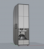
I've attached many pictures with updated Horn Response info, and screen caps from Rhino of the construction and one sheet layout.
To re-address some of the feedback I've already gotten, in no particular order:
- the current HR sim uses the semi-inductance model and other suggestions from Brian (thanks!)
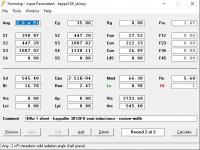
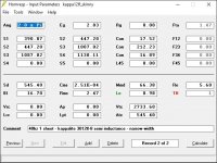
- the net volumes look good, in Rhino its 189379 cubic cm (189 liters), and in HR its a little smaller at 186.719 liters
- the compression ratio in HR is 1.22:1, which I'm assuming is a good match for the kappalite 3012lf driver (its lightweight and not that beefy)
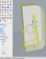
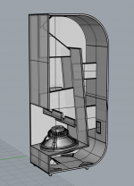
- I still plan to use 12mm plywood to keep the weight low, but I plan to use rabbet joints to increase the glue surface area to 18mm - you can see this in the screen caps
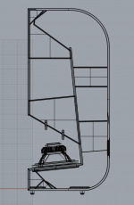
- I'm keeping the curves on the back - these will be done by scarfing two pieces of ply together and then using kerf bending. Aside from style points, this saves some material that is needed to just barely fit this all into one sheet
- I've included a reinforcing ring of plywood to the driver baffle to double it up for the fasteners
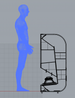
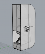
- if I can keep the weight to 50 lbs, I don't think casters are necessary, though I've included some standard recessed handles
- I'm less concerned about optimizing the dimensions to fit in vans or trucks, and more interested in optimizing for a one sheet design - so I'm keeping the height at 48" etc.
- I'm assuming the max voltage will be 35 volts, I plan to drive it with a 3eAudio chip amp, this keeps the driver displacement within the xmax.
Again, thanks for the all the good thinking thus far - and I appreciate any additional thoughts any of you might have.
Michael
- reduce the physical width as much as possible just allowing enough room for the driver, the overall cabinet width is now 13.5" (34.15cm)
- and adjusting the other dimensions to get flat response back down to 40hz
I've attached many pictures with updated Horn Response info, and screen caps from Rhino of the construction and one sheet layout.
To re-address some of the feedback I've already gotten, in no particular order:
- the current HR sim uses the semi-inductance model and other suggestions from Brian (thanks!)
- the net volumes look good, in Rhino its 189379 cubic cm (189 liters), and in HR its a little smaller at 186.719 liters
- the compression ratio in HR is 1.22:1, which I'm assuming is a good match for the kappalite 3012lf driver (its lightweight and not that beefy)
- I still plan to use 12mm plywood to keep the weight low, but I plan to use rabbet joints to increase the glue surface area to 18mm - you can see this in the screen caps
- I'm keeping the curves on the back - these will be done by scarfing two pieces of ply together and then using kerf bending. Aside from style points, this saves some material that is needed to just barely fit this all into one sheet
- I've included a reinforcing ring of plywood to the driver baffle to double it up for the fasteners
- if I can keep the weight to 50 lbs, I don't think casters are necessary, though I've included some standard recessed handles
- I'm less concerned about optimizing the dimensions to fit in vans or trucks, and more interested in optimizing for a one sheet design - so I'm keeping the height at 48" etc.
- I'm assuming the max voltage will be 35 volts, I plan to drive it with a 3eAudio chip amp, this keeps the driver displacement within the xmax.
Again, thanks for the all the good thinking thus far - and I appreciate any additional thoughts any of you might have.
Michael
Attachments
-
 Screen Shot 2021-03-07 at 1.36.38 PM.png466.6 KB · Views: 171
 -
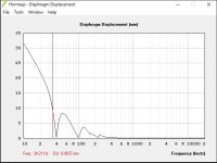 displacement_35volts.JPG46.7 KB · Views: 154
 -
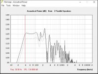 power_2speakers_35volts.JPG56.3 KB · Views: 148
 -
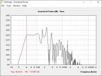 power_1speaker_35volts.JPG55.2 KB · Views: 138
 -
 HR_params_35volts.JPG66 KB · Views: 125
 -
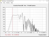 power_2speakers_2watts.JPG57.5 KB · Views: 139
 -
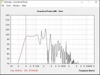 power_1speaker_1watt.JPG54.6 KB · Views: 136
 -
 HR_params_1watt.JPG65.4 KB · Views: 287
 -
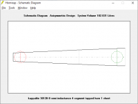
 schematic.JPG34.1 KB · Views: 175
Last edited:
...and some more image attachments.
Attachments
-
 Screen Shot 2021-03-07 at 2.01.20 PM.png159.5 KB · Views: 152
 -
 Screen Shot 2021-03-07 at 2.00.58 PM.png448.5 KB · Views: 150
 -
 Screen Shot 2021-03-07 at 1.43.11 PM.png180.8 KB · Views: 159
 -
 Screen Shot 2021-03-07 at 1.41.43 PM.png130.4 KB · Views: 152
 -
 Screen Shot 2021-03-07 at 1.40.44 PM.png209.6 KB · Views: 166
 -
 Screen Shot 2021-03-07 at 1.40.08 PM.png268.8 KB · Views: 169
 -
 Screen Shot 2021-03-07 at 1.39.30 PM.png272.2 KB · Views: 152
Last edited:
the current HR sim uses the semi-inductance model and other suggestions from Brian (thanks!)
As there are two parallel walls in every part of the path, the correct expansion options to use should be "Par", not "Con"
Thanks everyone for the feedback.
Brian:
I guess I'm confused about the expansion types - is it 'par' for all the segments? Is there a tutorial or article that better explains the different types and when to use each? And how the types correspond to real world example builds? I've corrected my sim to use 'par' - thanks.
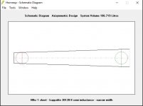
I also played around with boxplan to double check how I measured the hornpath and areas of my rhino model. I've attached screen caps of boxplan and the corresponding hr sim. Its a little different from my current rhino model, but the performance looks about the same in hr.
Does the boxplan info and the hr sim look ok to you? If so, I will update my rhino model and one sheet layout accordingly.
Thanks,
Michael
Brian:
I guess I'm confused about the expansion types - is it 'par' for all the segments? Is there a tutorial or article that better explains the different types and when to use each? And how the types correspond to real world example builds? I've corrected my sim to use 'par' - thanks.
I also played around with boxplan to double check how I measured the hornpath and areas of my rhino model. I've attached screen caps of boxplan and the corresponding hr sim. Its a little different from my current rhino model, but the performance looks about the same in hr.
Does the boxplan info and the hr sim look ok to you? If so, I will update my rhino model and one sheet layout accordingly.
Thanks,
Michael
Attachments

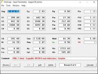

Yes, it will be "par" *(short for parabolic) for all the segments, as they are basically segments of rectangular cross-section, and consist of two parallel walls and two non-parallel walls. The expansion of the cross-section inside such a segment is parabolic in nature. You can check and confirm by "sampling" the cross-section at various points along the segment.
The design looks close enough.
The design looks close enough.
Following on to post #28, here are some attachments showing a 3D model and a one sheet plywood layout. I think this is dialed in enough to start cutting wood - I hope to do that soon. I'll update this thread when I do. Thanks.
Attachments
-
 Screen Shot 2021-03-16 at 9.36.49 PM.png187 KB · Views: 139
 -
 Screen Shot 2021-03-16 at 9.37.17 PM.png169.4 KB · Views: 127
 -
 Screen Shot 2021-03-16 at 9.39.32 PM.png265.1 KB · Views: 141
 -
 Screen Shot 2021-03-16 at 9.40.23 PM.png233.8 KB · Views: 141
 -
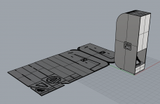 Screen Shot 2021-03-16 at 9.41.15 PM.png432.2 KB · Views: 138

And another thread left dangling .... was it attempted? Finished? Left to rot? What?
mBlanco Hi
How did it project come out. I have a Eminence lab12 6Ohm driver can I use in your design pros cons. Can you share plan cad file
How did it project come out. I have a Eminence lab12 6Ohm driver can I use in your design pros cons. Can you share plan cad file
does it was actually builded ?And another thread left dangling .... was it attempted? Finished? Left to rot? What?
- Home
- Loudspeakers
- Subwoofers
- 40hz Single Sheet Tapped Horn