Hi all, newbie here, with properly a silly question...
Looking at building the attached design, but with solid state PSU. If i have the calculations right B+ is at 470V, which is way above the 300 from the datasheet.
Is this right?, and just a function of the -20V fixed bias, quad EL84s and UL configuration?
Please help, confused ;-)
Looking at building the attached design, but with solid state PSU. If i have the calculations right B+ is at 470V, which is way above the 300 from the datasheet.
Is this right?, and just a function of the -20V fixed bias, quad EL84s and UL configuration?
Please help, confused ;-)
Attachments
What your schematic shows is not PP, it is PPP (parallel push/pull). Not that it makes any difference with regards to B+ limits.
What your schematic does not show are any of the component values, nor the specifications of any of the transformers, nor even the tube types for the rectifier and the driver stages. I can assume the output tubes really are EL84, since the title block of the schematic mentions it.
470VDC for B+ does seem much too high. My instincts agree with yours - I don't think the tubes will handle that much voltage in ultralinear. There are designers who have used such a high voltage (indeed, much higher even!) but those designs were pentode amps and the screen voltage was held much lower.
How did you arrive at that value for B+? Did you try to build some simulation of the power supply? Does your model include a sensible approximation of the circuit's total current draw? You should probably assume the amp is going to pull at least 150mA at idle.
parts and PSU
Thanks for the reply. I used PSU Designer II and the parts list. Full listing of parts below, plus the calibration proceedure (where i worked out the fixed bias rating)
Rated Power Output: 35 Watts
Frequency Response: 20Hz - 20kHz (+/-2dB)
THD: 0.5% (1kHz/35W)
Signal to Noise: 65dB (Input Shorted)
Input Sensitivity: 300mV
Treble Control: +16 ..-20dB
Bass Control: +18 ..-20dB
RESISTORS:
R1,R5,R8,R12,R16 = 1M
R2,R14,R18,R24,R25,R26,R27 = 1k
R3 = 82k
R4,R7,R13,R17,R19,R20,R21 = 100k
R6 = 150k
R9 = 220k
R10,R32 = 2.7k
R11 = 10k
R15 = 470R
R22,R23 = 330k
R28,R29 = 100R/1W
R30,R31 = 10R/1W
R34 = 27k/2W
R33 = 470k
R35,R36 = 10k/1W
R37 = 56k/0.5W
R38 = 22k/0.5W
P1 = 5M pot. lin.
P2 = 1M pot. lin.
P3 = 0.5 pot. audio taper
TR1,TR2 = 100K trimmpot
TR3 = 100R/0.25W wire wound trimpot.
CAPACITORS:
C1 = 0.047uF/100V
C2,C10,C14 = 47uF/16V
C3,C9 = 0.1uF/400V
C4,C5 = 47pF/50V cer.
C6,C7 = 4700pF/100V
C8 = 300pF/50V
C11,C13 = 0.033uF/400V
C12 = 0.033uF/100V
C15,C16 = 0.047uF/630V
C17 = 680pF/100V
C19 = 47uF/63V
C20 = 100uF/500V
C21,C22,C23 = 47uF/500V
T1 = Output Transformer - no data available
D1 = 1N4148
Power Transformer:
Secondary: 2 x 300VAC 240mA
Filament1: 5VAC/2A
Filament2: 6.3VAC/4A
Filament3: 6.3VAC/2A
Tubes:
V1,V2 = ECC83
V3,V4,V5,V6 = EL84
V7 = GZ34
Calibration Procedure:
Make sure all wiring and connections are correct. Remove tubes V3 - V6 from sockets,
leave only V1 and V2 inserted. Short amplifiers input to common ground.
1. Set both trimmpots TR1 and TR2 in center position.
2. Turn on power and check voltage at TP1, adjust with TR2 to ca. -20.0 Volts. Next turn off power
and insert all power pentodes.
3. Turn on power and let the tubes warm up. Connect DVM between TP2 and TP3 (control grids of the
pentodes), adjust with TR1 to zero Volts. Set DVM to 1 Volt scale and reset again to zero Volts.
4. Next connect DVM to common ground and one of the pentode cathodes, adjust with TR2 to 1130mV
(1.13V).
5. Now connect DVM between the V3 and V4 cathodes and adjust with TR1 to zero volts, use lower scale.
6. Finally measure voltage between common ground and cathodes of V3 and V4 pentodes. Should be 1130 mV
+/- 20mV. Repeat steps 3-5 if needed.
I couldn't find any data sheets that showed plate curves with Vg2 anywhere near the voltages you've described. I did put together a quick LTspice model. I can't say how realistic the model will be at those voltages, but it is the only thing I have.
With B+ at 470VDC and Vg1 = -20VDC, at idle I get 32.5 mA plate current and 2.5 mA screen current. Depending on the drop across your output transformer, that will be somewhere around 15 watts plate dissipation and 1.2 watts screen dissipation. That's a bit on the high side for an EL84.
If you tweak the bias voltage just a hair and bring it down to -21VDC, plate current drops quite a bit down to 23.6 mA. This might get your plate dissipation down to 11 watts, which is within spec. Screen current and dissipation drops too.
I think there were some old vintage receiver designs which ran the output tubes very hard. They might have used 7189A for the finals, or maybe they just ate through tubes like candy.
Thanks for the info, will definatley have a look at doing this. I am ordering the iron this week and want to nmake sure i don't have a pwr tranny that just turns out to be a valve killler.
Have you seen any interesting PPP at around 25-35 watts that should consider?
Have you seen any interesting PPP at around 25-35 watts that should consider?
I have to ask why two screens sharing one stopper?
Won't damp any parasitic modes that can ping-pong
between them.
I am still of the opinion that each and every screen,
grid, base, or gate should have 33R to 330R in close
proximity to spoil stub resonances. That would be in
addition to any larger value resistor needed for other
purpose, limiting the currrent or Miller lowpass. Large
value (over 800R) resistors act as open ends for RF,
don't much serve to spoil the local parasitic.
Your value 330R is good, but you need one for each
screen, to break up the dipole stub between them.
Tetrode screens and plates have nasty habit of
slight negative resistance kink in the "flat" curve.
Especially when secondary emissions get absurd.
Negative resistances love to oscillate on any and
every undamped resonance they can excite.
Pentodes have a supressor, but nothing is perfect.
470V how could you not have secondary emission?
You need those stoppers. Especially if you run the
device outside the window of sanity.
Else you might find it bursts into oscillation every
time the plate dips below the screen voltage.
When done deliberately, its called "Dynatron".
http://www.vias.org/basicradio/basic_radio_30_02.html
http://www.vtodorow.com/index.php?option=com_content&view=article&id=14&Itemid=17
Last edited:
Malcomfraser,
Since your power transformer has a secondary voltage of 300-0-300 VAC and you are using a capacitor input filter, I believe you have an error in your B+ calculation. I would expect the B+ loaded down to be on the order of 350V or so. With no load on this power supply type, I would expect you to see 424V. When you subtract the drop that will come with all tubes in place and the supply loaded through the rectifier tube and the secondary winding resistance losses, it should be more like 350V or so.
Mickeystan
I used PSU Designer II and the parts list.
Power Transformer: 2 x 300VAC 240mA
4. Next connect DVM to common ground and one of the pentode cathodes, adjust with TR2 to 1130mV.
Just a few key details from your last post...
If you build a 5AR4 rectified cap input supply out of a 600VCT power transformer (2x300) and then draw 240mA from it, you will end up with a B+ somewhere around 360VDC. Assuming the rectifier can handle that load, the resulting voltage is reasonable. It's almost exactly the same voltage used in ultralinear 6BQ5 designs such as the Dynaco Stereo 35 and SCA-35.
If you follow the biasing procedure, you are dropping 1130mV across the 10 ohm bias set resistor R30 (or R31). That's 113mA for a pair of output tubes, or 56.5 mA per tube. Entirely too high for the 6BQ5 - your overall dissipation will be greater than twenty watts per tube! I think I must have misinterpreted the biasing procedure... I will have to go back again and follow more carefully.
OK, so how embarrassing is that!! Now I really feel stupid!!
When I did the design on the PSU Designer II, I didn’t think about load, just plugged in the voltage in and hit simulate. Dah, clean forget about the load.
When I did the design on the PSU Designer II, I didn’t think about load, just plugged in the voltage in and hit simulate. Dah, clean forget about the load.
If you build a 5AR4 rectified cap input supply out of a 600VCT power transformer (2x300) and then draw 240mA from it, you will end up with a B+ somewhere around 360VDC.
I am using a Hammond 372JX feeding a Simple P-P board. (5AR4 rectifier 2 X 12AT7 and 4 X EL84). My B+ is 357 volts. Good quality EL84's (I use JJ's) don't have a problem with this voltage on plates and screens but the cheap stuff sold on Ebay glows brightly! I am using cathode bias (12 volts) so the tubes see only 340 volts or so.
Hammond power transformers always give you a few extra volts so the 300-0-300 volt transformers are really about 320-0-320.
On the bias calcualtions isn't the max cathode bias for a EL84 65mA?
On the very first page of the GE datasheet for 6BQ5, they do indeed specify the Maximum Rating for DC Cathode Current as 65 mA. Just a few lines up above they also clearly indicate the maximum plate dissipation = 12 watts and continuous screen dissipation = 2 watts.
If you have 360 volts across the tube, you need to keep the idle current under 39 mA to stay within the 14 watt overall dissipation limit (360V x 0.039A = 14 watts).
Hi!
Schematic is correct and will work without problems.
Do not know where you put voltage 470V ????....
Power transformer has a secondary and double alternation 2X300V~ rectificator tube.Tensione after rectificator-tube, continuous (DC) by filtering capacitors that if recovery is not solid-state (U ~ x1,41 = Udc), due to high internal resistance of the tube rectifier point B1 tension will be U ~ x1,3 approximately 390V at no-load consumption.
The task is likely to decrease voltage 360-350V (U B1). So the assembly will work very well.
As a recommendation, after you measure all voltages without the vacuum tube to be put on pedestals, it is desirable position to be half of Tr1 and Tr2's cursor to be to the end anode diode D1, which is the maximum negative voltage.
Regulating Tr2,the voltage measured on R30 or R31 corresponding to a current through the final tubes should not exceed the data from the catalog.
You must consider that there are many two tubes in parallel, so we measured the current split in half.
I hope I did understand.
great advice, thanks
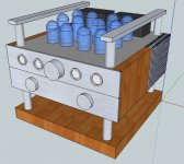
Wow love this Forum, thanks guys for all the great advice. So, final PSU design would look like:
The PSU spec is 360 volts for B+,
Seperate fixed bias supply that is adjustable (LM337),
A nice wad of 6.3 VDC for the heaters.
Throw in a softstart
And finally add a standby switch that drop the heater supply from 6.3 volts to 4 VDC (ala Morgan Jones's comprehensive PS) and we are good to go.
overall design concept attached, will now go away and draw up the PSU Schema, more to follow, very soon.
Attachments
Wow love this Forum, thanks guys for all the great advice. So, final PSU design would look like:
The PSU spec is 360 volts for B+,
Seperate fixed bias supply that is adjustable (LM337),
A nice wad of 6.3 VDC for the heaters.
Throw in a softstart
And finally add a standby switch that drop the heater supply from 6.3 volts to 4 VDC (ala Morgan Jones's comprehensive PS) and we are good to go.
overall design concept attached, will now go away and draw up the PSU Schema, more to follow, very soon.
Hi!
My guess is they do not justify feeding tubes with indirect heating in DC, were invented precisely this indirect heating tubes to be fed in AC (!!!)
DC heating is justified in only indirect heating tubes used in tube preamps for high-sensitivity microphone or gauges.
A neat and well planned assembly point will operate with zero noise due to AC powered filaments.
It's just my opinion!
Success in building the proposed project!
Schematic is correct and will work without problems.
...the voltage measured on R30 or R31 corresponding to a current through the final tubes should not exceed the data from the catalog. You must consider that there are many two tubes in parallel, so we measured the current split in half.
The only component I see between ground and V3 cathode is the 10 ohm resistor R31. Similarly, the component from ground to V4 cathode is 10 ohm R30. I do acknowledge that V3 and V5 are tied together, so whatever current is measured through R31 is for both tubes. Likewise, V4 and V6 are tied together so they share the current through R30.
V=I*R. If you have 1130mV across 10 ohms, current must be 113mA. Assuming they share equally, the current across each tube would be 56.5mA.
P=I*V. With 360 volts across the tube you have 0.0565 amps times 360 volts which equals 20.34 watts. By all rights that will be a well done tube in a very short order. Is there something I am missing?
R30,R31 = 10R/1W
Calibration Procedure:
6. Finally measure voltage between common ground and cathodes of V3 and V4 pentodes. Should be 1130 mV +/- 20mV. Repeat steps 3-5 if needed.
The EL84's are rated at 12 watts plate dissipation. This circuit is pushing the tubes to near their maximum. I'd back-off on the B+ voltage a bit.
The only component I see between ground and V3 cathode is the 10 ohm resistor R31. Similarly, the component from ground to V4 cathode is 10 ohm R30. I do acknowledge that V3 and V5 are tied together, so whatever current is measured through R31 is for both tubes. Likewise, V4 and V6 are tied together so they share the current through R30.
V=I*R. If you have 1130mV across 10 ohms, current must be 113mA. Assuming they share equally, the current across each tube would be 56.5mA.
P=I*V. With 360 volts across the tube you have 0.0565 amps times 360 volts which equals 20.34 watts. By all rights that will be a well done tube in a very short order. Is there something I am missing?
Right!
V3 and V5 were parallel to the ground through R31 katod.
V4 and V6 were parallel to the ground through R30 katod.
You thought very well, but do not know where you pulled that current, because, as is done in the divider R37 and R38, R38 have a voltage on 100V ~, so rectifier diode D1 (half-wave) and the C10 will have a filtration a voltage above 60Vdc negativity, so we can choose any anodic current through the four EL84 tubes.
As you think is very fair, the anode power dissipation of a single lamp is too high.
Voltage setting is very broad negativity, so we can choose very accurately.
I said above that do not exceed the EL84 anode power dissipation given in the catalog.
Hi,
I noticed first cap after rectifier is 100uF. Will kill older rect. and new ones right away . Should be 30uF for long life.
RCA SP-20 amp may be worth looking at as feedback setup is said to be better by others on this form and others. Should be able to use EL-84 tubes in it. It was recommended to swap 12AU7 for 6SN7 & 6AU6 for 6EJ7/EF184 for improved sonics. May need a preamp though! Has been said to sound great!
Good luck
Last edited:
Hi all, newbie here, with properly a silly question...
Looking at building the attached design, but with solid state PSU. If i have the calculations right B+ is at 470V, which is way above the 300 from the datasheet.
Is this right?, and just a function of the -20V fixed bias, quad EL84s and UL configuration?
Please help, confused ;-)
Hi!
I think it is interesting and schematic, which are much more time ... but it's in German!
http://www.jogis-roehrenbude.de/Verstaerker/4xEL84-30Watt.htm
Very good observation: Data Catalog for GZ34 say 60uF filtering capacitor is maximum at 300Vac.
Attachments
Last edited:
- Status
- Not open for further replies.
- Home
- Amplifiers
- Tubes / Valves
- 4 x EL84 in UL PP, 470 B+!! is this right