My FIR crossover slope would be 100+dB/oct, so hopefully I can avoid or mitigate some problems with this.
I am curious about what problems you think it might avoid? Are you aware of any speakers that have used such steep slopes before?
I'd like to steer the discussion to the fundamental of this design - the bass module. For now, let's assume 2x 8" drivers mounted on a narrow tall as-deep-as-necessary box. I don't know how much edge rounding I can do, so for now just simple cubic object. I rounded up some candidate bass drivers as below:
I am excluding non-paper materials for now to go safe for my subjective taste.
| Sen | siti | vit | y@ | Hz | Max Power | Xmax | Sealed Volume | F3 | Price | |||||||
| Driver | Fs | 50 | 60 | 70 | 80 | 90 | 100 | 140 | 200 | 240 | 300 | |||||
| Satori MW19P-8 | 32.5 | 79 | 83 | 85 | 87 | 86 | 87 | 88 | 89 | 88 | 90 | 70(rated) | 13.4 | 0.32 | 73 | 197 |
| SB SB20PFCR30-8 | 34 | 80 | 85 | 88 | 89 | 88 | 88 | 90 | 89 | 90 | 91 | 50(rated) | 11.5 | 0.5-0.75 | 70 | 54 |
| SB SB23NRXS45-8 | 27 | 84 | 85 | 87 | 88 | 88 | 89 | 90 | 88 | 88 | 88 | 60(rated) | 13 | 0.75 | 55 | 109 |
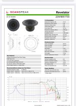
| Scanspeak 22W/8851T | 21 | 82 | 87 | 85 | 86 | 87 | 86 | 87 | 87 | 87 | 87 | 80(IEC 18.4) | 18 | 0.7 | 57 | 381 |
| Scanspeak 21W/8555-10 | 20 | 83 | 87 | 85 | 87 | 87 | 87 | 87 | 88 | 87 | 87 | 100(IEC 18.4) | 13 | 0.5 | 59 | 274 |
| Seas Excel W22NY-001 | 33 | 80 | 83 | 84 | 85 | 86 | 86 | 87 | 87 | 88 | 90 | 90 | 14 | 0.35 | 100 | 325 |
| Seas Excel W22NY-003 | 21 | 82 | 84 | 86 | 86 | 87 | 87 | 86 | 87 | 88 | 88 | 200 | 14 | 0.5 | 68 | 580 |
| Seas H1471 | 34 | 80 | 83 | 85 | 86 | 87 | 87 | 88 | 88 | 90 | 90 | 90 | 12 | 0.5 | 95 | 190 |
| Seas CD22RNX | 20 | 79 | 82 | 83 | 84 | 85 | 85 | 85 | 85 | 85 | 85 | 100 | 14 | 0.4 | 73 | 160 |
| Volt B220.2 | 32 | 80 | 83 | 85 | 87 | 89 | 90 | 90 | 90 | 90 | 88 | 150(AES) | 10.5 | ? | ? | 223 |
| Volt BM228.8 | 35 | 83 | 84 | 84 | 87 | 88 | 88 | 90 | 89 | 90 | 90 | 150(AES) | 8 | ? | ? | 215 |
I am excluding non-paper materials for now to go safe for my subjective taste.
Any reason you are looking at all these drivers sealed? Seems to me you are going to need a sub depending on how low you want to go. You going 3 way or 3.5 way?
Rob 🙂
Rob 🙂
You wouldn't want to use 3D sound simulation software like akabak to tackle the full problem in a cheaper, quicker and more flexible manner? (Subject of course to having the software and knowing how to use it.) I am not familiair with vituixcad but the diffraction is almost certainly a fairly approximate one based on diffraction from edges.
As I mentioned in post #218 https://www.diyaudio.com/community/threads/4-way-instead-of-3-way.413297/post-7701314
In my case, I find it easier and more enjoyable to build and test a prototype baffle rather than run BEM simulations. I do a lot of simulating at the start of a project, and once I make all my driver measurements, there is a lot more simulations to design the crossover. I spend enough time at a computer screen as it is, so I like the "build prototype and test" aspect.
Regarding the diffraction model in VituixCad. It may be a simplified approximation, but I have found it accurate enough for design purposes. This is based on comparisons of the predicted diffraction response compared to the actual measured response, using both tweeters and small cone drivers.

On the last quote l was looking at the B&W 801 D4 bass enclosure when l did the sketch.
Bear in mind the B&W had no dsp. But
Bear in mind the B&W had no dsp. But
Yep, I'm aware of 'em.🙂I am curious about what problems you think it might avoid? Are you aware of any speakers that have used such steep slopes before?
I've used LR 96dB/oct linear-phase routinely, on dozens of projects for about 10 years.
Problems they overcome/advantages:
They allow drivers to be used exclusively in their "sweet bandwidth" where mag is flat, and consequentially phase is naturally flat too.
They reduce lobing by reducing the frequency range of critical summation.
They are damn easy to implement, because impulse peaks align which are easy to identify.
Unlike IIR filters that must have initial impulse rises properly identified. Almost impossible with low frequencies.
They don't change time and phase relationships when changing the crossover frequency (again, like IIR does)
They reduce phase rotations, and make group delay between driver sections equate simply to time-of-flight between sections.
And they rock, because they make it easy for anyone to achieve excellent results. 😀
No more slippery-slope, hoo-doo voodo IIR crossovers to contend with.
Here's an example of a 5-way measured today.
Individual sections mag and impulses, with xovers at 100, 250, 750, & 4000Hz, all 96 dB/pct.
All below indoors 1m no gating. Sub and main spliced.
Measured full speaker. 1/48th
You go and good luck, jheoaustin !
Hi Jheaustin,
To answer your earlier post:
The slope was to create a windswept surface below the mid range driver. It will allow tweaking of the mid range enclosure forward after position.
Yes tilting driver optimises the on and off axis dispersion on the vertical plane where you have a long array. I would not recommend 3 drivers in mid/ hf unless your listening at 3 metres or more distance.
Under hung voice coils are in some respects better but they are expensive and can be less efficient than over hung designs.
On the ATC mid does anyone have measurements of the off axis performance?
On your list of 8 inch woofers any online simulator will give you an idea of enclosure size, bass extension and max output at low frequencies.
My suggestion is to obtain another pair of 2500.1 10 inch woofers.
They are more displacement, 35000 mm3 versus 22700 mm3, they are more efficient.
One of the differentiators from your prior system needs to be scale. Scale is not just bass authority, but about opening up the layers in a mix. To do this you need to match the capabilities of the ATC dome with something equally capable in the bass.
I think I've seen the off axis performance of ATC mid in the 4th edition of P. Newell 'Recording Studio Design'.
There is a whole section about it iirc.
I will take alook tomorrow.
Meanwhile Troels Gravesen have some measurements:
http://www.troelsgravesen.dk/ATC-SM75-150.htm
The SCM110A i had for mains wasn't bad at all but the larger SCM200and 300 kicked .ss!
The 3 have great transparency but obviously the 2x15" goes lower with less distortion in low end. The 110 needed closer listening distance.
That said the most impressive results i've heard from ATC mids were older Quested with 4x15" HM415( Volt bass drivers).
Since they shifted to Volts mid.
All of them are wide baffle.
Scm300 and Quested were inwall...
Last edited:
Another system i've heard using ATC mid were Exigy.
1x15" ( Tad) +ATC mid+ tweeter.
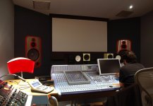
Inwall too in a room designed by Exigy ( former brand of owner was Boxxer). Dsp with BSS loudspeaker management unit. Circa 2010 at Karism sound in Paris. Great sound, one of the best control room in town at that time.
1x15" ( Tad) +ATC mid+ tweeter.
Inwall too in a room designed by Exigy ( former brand of owner was Boxxer). Dsp with BSS loudspeaker management unit. Circa 2010 at Karism sound in Paris. Great sound, one of the best control room in town at that time.
Attachments
I had a look at the woofer list.
The best were either of the Scanspeak or the Volt woofers. The others aren’t worth thinking about. The Scan drivers have low inductance which is good indicator of a well engineered driver.
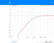
The simulation of a woofer in an enclosure is fairly matter of fact below 100 hertz. I would recommend a flat baffle supporting both woofers. Despite your desire for a narrow baffle it will still help load the drivers near the floor.
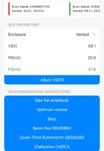
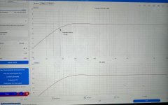
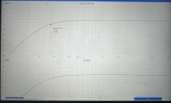
Because you’re only going up to 400 hertz your best bet is to place one woofer in it’s sealed volume and the other in an optimal vented alignment.
This will give you depth and speed in your bass.
In essence your sealed woofer acts as a mid bass driver. The sealed woofer is at the top with the vented woofer near the floor.
Halve the volume in the screen shot for a single woofer in a vented enclosure.
Add you floor loading and you have quite a robust low frequency system down to the low 30’s. I would rear vent the port as it will be a reasonable length in this size enclosure.
The best were either of the Scanspeak or the Volt woofers. The others aren’t worth thinking about. The Scan drivers have low inductance which is good indicator of a well engineered driver.
The simulation of a woofer in an enclosure is fairly matter of fact below 100 hertz. I would recommend a flat baffle supporting both woofers. Despite your desire for a narrow baffle it will still help load the drivers near the floor.
Because you’re only going up to 400 hertz your best bet is to place one woofer in it’s sealed volume and the other in an optimal vented alignment.
This will give you depth and speed in your bass.
In essence your sealed woofer acts as a mid bass driver. The sealed woofer is at the top with the vented woofer near the floor.
Halve the volume in the screen shot for a single woofer in a vented enclosure.
Add you floor loading and you have quite a robust low frequency system down to the low 30’s. I would rear vent the port as it will be a reasonable length in this size enclosure.
Attachments
Last edited:
In essence your sealed woofer acts as a mid bass driver. The sealed woofer is at the top with the vented woofer near the floor.
Really what's the point of choosing low FS drivers with decent x-max and running sealed no EQ? I was thinking L7 with a ported 12 on the side or a 2.5 way to cover baffle step and better DI match at crossover without the lobing running a pair full range. Well lets see what happens.
Best of luck to the OP which ever way you go.
Rob 🙂
Hi Rob,
Horses for courses.
DI match at 400 hertz crossover point from the woofer??
Baffle step with a low pass cross over 400 hertz with two stacked 8 inch woofers. If there is simply EQ out. The dual woofers will candle it.
It’s an approach to obtaining a Bessel vented alignment which is quite difficult to do because of the exact QTS valve required.
Sealed enclosures have inherently better transient attack. That is beyond question. So do transmission lines because the line has a low Q spread over a broader frequency range. Thats the explanation from PMC in the UK who have refined the transmission line.
By operating both a seal and a vented enclosure together it’s possible to get the best of both. I personally owned a commercial consumer system using 6.5 in Scan woofers using the approach and it was excellent.
I wouldn’t default to EQ until assessment in the users own room.
Last edited:
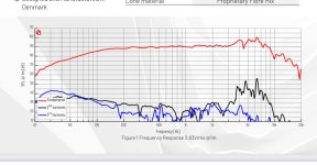
If the ATC mid dome falls through l would suggest the Purifi 6 inch mid range driver. There are several versions. The higher efficiency one. They have very low distortion and apparently don’t have a sound.
Below is an impartial test report by Vance Dickason
https://audioxpress.com/article/test-bench-the-ptt6-5m08-nfa-01-6-5-midrange-from-purifi-audio
The B2 simulation gives be a 5L sealed enclosure . It has a peak Xmax of 6 mm
The data sheet with full disclosure
They also provide data you can import into a simulator for design work
https://ptt.purifi-audio.com/web/content/product.template/271/x_studio_data_sheet?download=1
https://ptt.purifi-audio.com/web/co...quency_response_and_impedance_data?download=1
Attachments


DI match at 400 hertz crossover point from the woofer??
Look at the polars F-206/208. That lower crossover 270/300? point helps define the slope for the DI. I have 15's and horns in my head so!
Rob 🙂
And that pretty Bessel alignment goes out the window as soon as you start using the system at normal volume or placing the speakers in a normal living room, because of the typical non-linearities of the T/S parameters and low freq behaviour of the room. So obtaining an alignment like this have little to no practical value IMO.It’s an approach to obtaining a Bessel vented alignment which is quite difficult to do because of the exact QTS valve required.
Sealed enclosures have inherently better transient attack. That is beyond question. So do transmission lines because the line has a low Q spread over a broader frequency range. Thats the explanation from PMC in the UK who have refined the transmission line.
I didn't see any measurements that backs up PMCs claim. Instead the low freq responses of it's speakers is wobbly, with high Q resonances.
https://www.stereophile.com/content/pmc-fact8-signature-loudspeaker-measurements
Well we all have our own interpretation of what is what. You can tear down how well a Bessel sealed or vented alignment works but that is not the point of these discussion. If it was a project would be going is circles for an eternity.
The simple fact is that a low Q alignment either sealed or bass reflex BB4 alignment will more often than not work better in any random listening room than a maximally flat base reflex tuning. This is because the earlier low frequency roll off is counted by the natural loading of a floor, a door and wall or a corner in what is referred small room acoustics. This can be graded into +3,+6, +9 db below 100 hertz. Every room is bit different and the actual location of the woofer transducer relative to the wall and floor effects the low frequency augmented response.
Most users experience this phenomenon.
Buy many hifi fanatics mistake the boom of a bass reflex system as slow or resonant because of the design. Referring to the above explanation it's the flat response of the low F3 in the room that is stimulating model resonances. These resonances have a time related dimension referred as ringing. The import criteria here is the low frequency absorption coefficient of a given room at home. The more LF absorption the quicker the resonance is damped. This is low bass traps work.
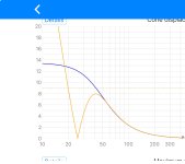
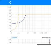
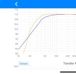
See the attached graphic.
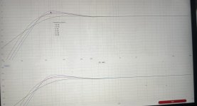
In this screen shot I have shown a sealed enclosure in free space and then added a +3 db LF self EQ below 100 hertz
I have then overlaid several bass reflex alignments including maximally flat, optimal and the BB4. The bass reflex alignments obviously end up with a hump in the response. This is quite audible because the ear is sensitive changes in LF amplitude
Generally common sense prevails and a user will move the enclosure to a location that while a compromise will have the smoothest overall bass response. On paper as in an REW an measurement every square foot in a room will show different snap shot of the bass response and the time domain room modal resonances. Only in a large acoustic room can these problems be ignored (larger than an indoor gym).
But if a diy builder wants a sealed system then that is on the menu. I firmly believe (sorry for the pun) that a sealed woofer can produce a more articulate mid or upper base because the system has the counter pressure of the enclosure. This is exactly the effect of adding a mid bass woofer just like in the L 250. But to simplify the implementation here for our friend I am suggesting to run the sealed enclosure over the same bandwidth of the vented enclosure. The vented enclosure can be tuned to a BB4 alignment which also has a response that tappers off early. The port doesn't become active until well below 30 hertz typically .
Yet another option of more experienced builders is a passive radiator aka Celestion Ditton 66 & 44 fame. In this implemented the passive radiator replaces the port. Above the tuning frequency of the passive radiator the enclosure is for all intentions sealed. These designs are coming back in both consumer hifi and near field monitors. They work very well when correctly engineered. But it more difficult to tune a radiator Han a ported bass reflex system
The simple fact is that a low Q alignment either sealed or bass reflex BB4 alignment will more often than not work better in any random listening room than a maximally flat base reflex tuning. This is because the earlier low frequency roll off is counted by the natural loading of a floor, a door and wall or a corner in what is referred small room acoustics. This can be graded into +3,+6, +9 db below 100 hertz. Every room is bit different and the actual location of the woofer transducer relative to the wall and floor effects the low frequency augmented response.
Most users experience this phenomenon.
Buy many hifi fanatics mistake the boom of a bass reflex system as slow or resonant because of the design. Referring to the above explanation it's the flat response of the low F3 in the room that is stimulating model resonances. These resonances have a time related dimension referred as ringing. The import criteria here is the low frequency absorption coefficient of a given room at home. The more LF absorption the quicker the resonance is damped. This is low bass traps work.
See the attached graphic.
In this screen shot I have shown a sealed enclosure in free space and then added a +3 db LF self EQ below 100 hertz
I have then overlaid several bass reflex alignments including maximally flat, optimal and the BB4. The bass reflex alignments obviously end up with a hump in the response. This is quite audible because the ear is sensitive changes in LF amplitude
Generally common sense prevails and a user will move the enclosure to a location that while a compromise will have the smoothest overall bass response. On paper as in an REW an measurement every square foot in a room will show different snap shot of the bass response and the time domain room modal resonances. Only in a large acoustic room can these problems be ignored (larger than an indoor gym).
But if a diy builder wants a sealed system then that is on the menu. I firmly believe (sorry for the pun) that a sealed woofer can produce a more articulate mid or upper base because the system has the counter pressure of the enclosure. This is exactly the effect of adding a mid bass woofer just like in the L 250. But to simplify the implementation here for our friend I am suggesting to run the sealed enclosure over the same bandwidth of the vented enclosure. The vented enclosure can be tuned to a BB4 alignment which also has a response that tappers off early. The port doesn't become active until well below 30 hertz typically .
Yet another option of more experienced builders is a passive radiator aka Celestion Ditton 66 & 44 fame. In this implemented the passive radiator replaces the port. Above the tuning frequency of the passive radiator the enclosure is for all intentions sealed. These designs are coming back in both consumer hifi and near field monitors. They work very well when correctly engineered. But it more difficult to tune a radiator Han a ported bass reflex system
Attachments
Yes, it's audible, because there is no such thing as optimal bass reflex (or other type of box-loading) alignment without context.I have then overlaid several bass reflex alignments including maximally flat, optimal and the BB4. The bass reflex alignments obviously end up with a hump in the response. This is quite audible because the ear is sensitive changes in LF amplitude
Yep, I'm aware of 'em.🙂
I've used LR 96dB/oct linear-phase routinely, on dozens of projects for about 10 years.
And they rock, because they make it easy for anyone to achieve excellent results. 😀
No more slippery-slope, hoo-doo voodo IIR crossovers to contend with.
Why have you opted for a flat on-axis passband? Wouldn't it benefit from a degree of adjustment in the manner of B&W in order to move the perceived timbre more towards neutral/natural? Or is the speaker perhaps a stack of horns?
We agree to disagree and l am perfectly fine on that. I do think you’re confusing the issue.
The Q of the alignment isn’t changed by the room. What’s happening in the electro mechanical relationship with the driver and the enclosure isn’t affected by the room. That is the point of my post. A poorly tuned enclosure could be under damped or over damped.
The point is a good design attempts to accommodate real world acoustic in consumer systems. This has been the trend particularly with bass reflex tower systems over the past 20 years.
Bass reflex systems built originally did not account for the room boundaries. Unfortunately many diy loudspeaker builders fall foul of this issue and design for a maximally flat response. A BB4 alignment or simply selecting an appropriate sized driverwith appropriate sized with specific TL parameters can produce a much smoother in room response for the consumer.
Designing a bass reflex system to be maximally flat to 30 hertz can end up being a boom box if the enclosure cannot be located to a position with a smooth bass response.
No two rooms are ever the same in reality and it’s the users responsibility to use correction such as Dirac. This is well explained by Gene on Audioholics.
Last edited:
- Home
- Loudspeakers
- Multi-Way
- 4-way instead of 3-way?