I guess a straight up box with a 10" woofer is kind of big baffle
Going even further you can mount wings on the edges, and you have a genuine wide baffle, magic
A world famous designer from japan do that with his "high-end" speakers - use some hard wood with smooth round edges and they could turn into real lookers
Going even further you can mount wings on the edges, and you have a genuine wide baffle, magic
A world famous designer from japan do that with his "high-end" speakers - use some hard wood with smooth round edges and they could turn into real lookers
Hi guys,
Tinitus, re: "wings on the edges" -- you must be psychic! I was already designing just that! Cool, that you mentioned it!
Everyone,
I'm sorry if I've missed replying to your messages. I've been busy simming the FRC data that *Curt* very kindly provided me for the drivers (a monumental effort on his part!). Thanks heaps Curt!
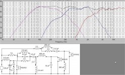
Simmed FRC data was for my existing boxes / baffles. My first xo attempt is attached. The xo is a mix of Troels PMS / 3WayClassic and my own tweaks. Parts count is high, unfortunately. Also, an LCR trap for the mid was required to get this response. I'll look at Sretens series/parallel mix later. It is of course open for critique and any comments would be most welcome as usual.
The Z-driver-offsets were from Roman B at 10 feet - I hope I did it right in SW? XO-points are about 440 and 2900Hz. I couldn't get 440 down to 290 with a smooth response. Any comments most welcome please. But I haven't looked at impedance/phase just yet. thanks and cheers! grant
Tinitus, re: "wings on the edges" -- you must be psychic! I was already designing just that! Cool, that you mentioned it!
Everyone,
I'm sorry if I've missed replying to your messages. I've been busy simming the FRC data that *Curt* very kindly provided me for the drivers (a monumental effort on his part!). Thanks heaps Curt!
Simmed FRC data was for my existing boxes / baffles. My first xo attempt is attached. The xo is a mix of Troels PMS / 3WayClassic and my own tweaks. Parts count is high, unfortunately. Also, an LCR trap for the mid was required to get this response. I'll look at Sretens series/parallel mix later. It is of course open for critique and any comments would be most welcome as usual.
The Z-driver-offsets were from Roman B at 10 feet - I hope I did it right in SW? XO-points are about 440 and 2900Hz. I couldn't get 440 down to 290 with a smooth response. Any comments most welcome please. But I haven't looked at impedance/phase just yet. thanks and cheers! grant
Attachments
Looks fine and should sound ok - but still dont understand why you reverse polarity on tweeter
May I suggest small adjustments to try, may work, may not
MID
try and make 43uf series cap a tad bigger (47uf)
and 600uH series inductor a bit smaller
Try a series resistor on 16uf paralel cap
I dont fully understand that you have both a series and parallel notch, and that you place them before filter - could you exsplain your trick
TWEETER
paralel 200uH, try a series resistor on it and maybe make it a bit smaller
BAS
Not sure its a good thing with the RC, 14uf/13R
Instead make 6.0mH series inductor a bit smaller
make paralel 58uf bigger (68uf ?), maybe with a series resistor on it
STANDARD resistor values - 1R2, 1R5, 1R8, 2R2, 2R7, 3R3, .... look up a catalogue from a supplier
Please Grant, try and sim with standard values, believe me it will sound better
Tinitus,
many thanks for your suggestions! I'll sim them and get back to you.
Yes, re resistor standard values - good point, and thanks, grant
many thanks for your suggestions! I'll sim them and get back to you.
Yes, re resistor standard values - good point, and thanks, grant
It looks to me that mids (and tweeter) were down 3db's on 3k.
Sorry I just came in and I didn't check the xover. I saw a lot of components there anyway.
Sorry I just came in and I didn't check the xover. I saw a lot of components there anyway.
Hi Inductor, Thanks for dropping in!
Yes, both the T and M 'in box' responses have a 3dB dip from 2 to 5K,
which is probably diffraction effect due to non optimal driver placements on the baffle. Too many parts I know! When I get time I'll try to sim Sreten's mixed series/parallel xo suggestion to see if it helps. thanks, grant
Yes, both the T and M 'in box' responses have a 3dB dip from 2 to 5K,
which is probably diffraction effect due to non optimal driver placements on the baffle. Too many parts I know! When I get time I'll try to sim Sreten's mixed series/parallel xo suggestion to see if it helps. thanks, grant
Hi guys,
I value your input very highly, but I do have a tendency to 'chop and change' at whim in the hope of discovering new things and better solutions. As a relative beginner still, I think there is value in
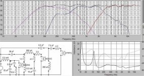
my approach....I hope. Unfortunately, I've not had as much time as I'd like to do much simming lately. (my mum just broke her leg). However, my latest, slightly more 'amp-friendly' and hopefully ok xo is attached. I really want to thank you guys..Sreten, Omni ,Tinitus and Curt (in no order) for your incredibly kind help so far!
Tinitus,
I'm sorry I haven't pursued your suggestions as yet. But I definitely will! I'm very thankful for your previous suggestion of resistors in series with parallel components! From the simming I've done so
so far (attached is my simplified latest) - it really does make a difference! Thanks very much indeed.
Re: "I dont fully understand that you have both a series and parallel notch, and that you place them before filter - could you exsplain your trick".......I'm confused too! lol. I just copied and modified 2 Troels xo's. So its definitely MY error, and I'm emphasizing *not Troels*! I'll look into it, asap.
Omni,
Cheers mate, and thanks for your kind offer to 'sim' for me. Your results will be very interesting indeed. 'Frankie' seems very close now! Yeah, I can't wait!
Sreten,
I haven't forgotten your 'mixed' xo advice....its still on the 'to do' list...many thanks!
Curt,
Are you in here? You're very welcome to join us here of course.
Inductor,
Yes, and now I'm playing with a 3rd Order on the tweeter, hehe. Any suggestions please? Are you building a 3-way design?
I value your input very highly, but I do have a tendency to 'chop and change' at whim in the hope of discovering new things and better solutions. As a relative beginner still, I think there is value in
my approach....I hope. Unfortunately, I've not had as much time as I'd like to do much simming lately. (my mum just broke her leg). However, my latest, slightly more 'amp-friendly' and hopefully ok xo is attached. I really want to thank you guys..Sreten, Omni ,Tinitus and Curt (in no order) for your incredibly kind help so far!
Tinitus,
I'm sorry I haven't pursued your suggestions as yet. But I definitely will! I'm very thankful for your previous suggestion of resistors in series with parallel components! From the simming I've done so
so far (attached is my simplified latest) - it really does make a difference! Thanks very much indeed.
Re: "I dont fully understand that you have both a series and parallel notch, and that you place them before filter - could you exsplain your trick".......I'm confused too! lol. I just copied and modified 2 Troels xo's. So its definitely MY error, and I'm emphasizing *not Troels*! I'll look into it, asap.
Omni,
Cheers mate, and thanks for your kind offer to 'sim' for me. Your results will be very interesting indeed. 'Frankie' seems very close now! Yeah, I can't wait!
Sreten,
I haven't forgotten your 'mixed' xo advice....its still on the 'to do' list...many thanks!
Curt,
Are you in here? You're very welcome to join us here of course.
Inductor,
Yes, and now I'm playing with a 3rd Order on the tweeter, hehe. Any suggestions please? Are you building a 3-way design?
Attachments
Hi.
Yes... a 3-way design.
Well, I don't think you will need a 3.order because your Fs on the tweeter is really low and the freq. on the xover is really high. I don't see any need for that unless.... there are some tricks sometimes.
I didn't check the xover on this page, I will check after this. Afterwall, are you using the same speakers you mention lately,
Vifa p25wo0008, Seas mca15rcy08, SEAS 27TFFC06 (?).
I just checked.
Ps: Is your mid on the side of the woofer or on top? If on the side they may cancel in some spots of the room and at some frequencies, maybee problematic, mainly between 200Hz and 600Hz.
Do you have the frequency output curves for the 3 speakers. Just looking because I didn't find any. Did you published them here that I didn't look? Regards.
Hi Inductor,
Many thanks! Yes the same drivers P25WO , MCA15 and 27TFFC (Fs=550Hz). I agree about the tweeter, a 3rd order on tweeter may be unnecessary as you say, but initially the response looks better than my previous 2nd order. However, I could very well end up with 2-Order on it.
The driver placement in the 32cm by 74cm box (non optimal for P25) is drivers adjacent , that is, minimum vertical separation (T on top, then M then W). Both the T&M are horizontally offset about half way from centre to the box edge. I think the placement has caused the diffraction problem.
A very kind man called Curt (cc00541) in here did the did the box/baffle/diffraction simulations for me! His methodology is in this thread:
http://www.diyaudio.com/forums/showthread.php?threadid=96819&highlight=
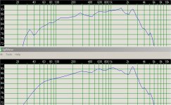
Curt sent me the manuf's data for each driver and also the response in my box. The files are attached. The manuf's data is on top and the 'my box' response is below. cheers and thanks, grant
Many thanks! Yes the same drivers P25WO , MCA15 and 27TFFC (Fs=550Hz). I agree about the tweeter, a 3rd order on tweeter may be unnecessary as you say, but initially the response looks better than my previous 2nd order. However, I could very well end up with 2-Order on it.
The driver placement in the 32cm by 74cm box (non optimal for P25) is drivers adjacent , that is, minimum vertical separation (T on top, then M then W). Both the T&M are horizontally offset about half way from centre to the box edge. I think the placement has caused the diffraction problem.
A very kind man called Curt (cc00541) in here did the did the box/baffle/diffraction simulations for me! His methodology is in this thread:
http://www.diyaudio.com/forums/showthread.php?threadid=96819&highlight=
Curt sent me the manuf's data for each driver and also the response in my box. The files are attached. The manuf's data is on top and the 'my box' response is below. cheers and thanks, grant
Attachments

Hi,
I just checked your post this morning (Europe). I am also looking at Curt's post page you mention.
In the meantime can you recheck the 27TFFC for the Fs resonance on 900Hz instead of the 550Hz you mention.😕
Doesn't bother me but to be sure of any modification on the tweeter.
Also, do you know of the new resonance for the mid w/the box you mention of 1.5 litre?
I will keep you updated, Regards.
Interesting,
I just got the new brochure for the 550Hz SEAS 27TFFC H0881 Tweeter. (Thanks)
Now, about the resonance frequency for the mid.
If you don't know, how are you going to chose the xover frequency to be over than that?
You are bringing in, problems of impedance, phase and design-of-the-filter problematic unknownes.
The cross section is or can be next to that frequency and in my opinion shouldn't.
Think about the tweeter in the same way, first the resonance frequency of 550Hz and after (higher) the xover frequency of 2500Hz.
You can control a resonant frequency with your active/passive filters but first you have to know which one, and after wall is better to let that problem with the woofer only if you can, and to let the mid breath 😱 over the xover frequency after you find it or have an idea at least wich one it is.
I would not mention this if... the xover frequency and mid response was over the 500/600Hz band and in your simulation it is very active already at 200-600Hz frequencies.
Inductor, Hi!
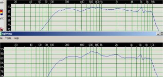
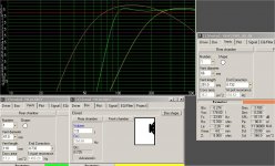
Just for fun, I tried WinISD again for my drivers. I hope I have entered the parameters correctly now. 'Orange' is the P25 in my existing 40 litre boxes (non optimal I know!), 'Green' is the MCA15 in a 4.3 Litre
vented box (similar to Troels PMS), it looks good to me. 'Yellow' is the MCA in the existing 1.5litre closed box that I was going to use. Yuck! - no bass extension. I think the 'Green' is the way to go....
(the P25 would need to be in a 75Litre box, including 4.3L for the mid-box, for best bass extension)....grant
Attachments
Hi Inductor,
Re: * Interesting *, from my very limited knowledge I hope I have understood your question? I think what you are saying is that the Mid and Woofers Fs will change in the new boxes? This seems reasonable to me, but by how much I wonder? The tweeter has its own 'box' so I suppose its unaffected.
The P25 Fs is 24Hz and the MCA15 Fs is 51Hz - manuf's specs. So I just blindly accepted that a lower xo-point of 300 to 380? Hz would be ok? I didn't realise other factors were significant. I thought some
'octave separation' is what is needed? So maybe 4 octaves from the P25 Fs to give a ~380Hz xo-point? If this 'logic' is correct the MCA should be crossed at about 800Hz! But , to me this seems way too high?
Mr Troels G's PMS design, which I'm hoping to partially emulate ( albeit different woofers ), has a 3kHz xo for the 27TFFC/MCA, and ~ 360Hz xo for the MCA/woofer. I hope I haven't missed the point of what you're advising me to do? Your knowledge in this would be very helpful to me! thanks, grant
I am reading your post. Give me some time. I am just trying to read between your sentences.
You said a vented mid... you don't need to do that because... well it is just a mid, not a woofer, and a closed box is all there is if you don't want to go "low" with your mid (like lower than 90Hz). That work you leave for the woofer and woofer box.
Second, the mid is about 160Hz Fsc, simulated with the help of WinISD, for 1,5L, in a closed box. I join here the picture.
So, is out of the way, but we have to check it later if it's phase is working well in the crossover (caps and inductors) and in conjunction with the woofer, not to cancel in opposition of phase.
As I said I am reading your post, and what I would like to know next is if you are working already with the xover components you showed before in your filter or you are buying new ones.
Don't forget... closed 1,5L box in the mid. If you had a 0,15L box (just as an example) your resonance Fs goes up to 450Hz. So, from your point of view you want to bring the mid as low as you can. It's ok. Can you elaborate a little. (Human voice is between +/- 90Hz-1000Hz)
Attachments
- Status
- Not open for further replies.
- Home
- Loudspeakers
- Multi-Way
- 3way XO help greatly appreciated!