Very nicely done. 
In terms of impedance - a low of about 3ohms is acceptable for a 4ohm speaker. But usually you can get the tweeter impedance higher than that. I can't quite see what the values you've used in the xo are but too low a value for L4 can sometimes be the cause. Or maybe just switch to series resistance instead of the L-pad if you want to raise the impedance in the tweeter section.
I might try to flatten the range from about ~250Hz to 800Hz just a little bit. That may depend on what your ears think is right and on the validity of the measurement you've posted.
Agreed, off-axis data wouldn't hurt.
In terms of measuring, maybe you might find these helpful:
In-room quasi-anechoic measurements
How to find the realtive acoustic centers with PCD
speaker-acoustic-center with XSim
Hello Everyone! I am back again...
Sorry for the huge delay... I have a new crossover design that I will love to share!
One doubt I have; a friend told me that I would be great to match the Impedance peaks on the graph. That it would be more "ideal".
I have been re-modeling the box tuning so I can match these peaks, altough, I do not notice a great change. I have to go with a larger port & lower Fs (24hz).
Did anyone had this experience? Is it better to match the acoustical box peak & the speaker peak. Or can the live together like this? Should I do it?
I am actually on time for enclosure changes.
Love to hear your thoughts!
Again the Drivers used:
- SCANSPEAK R2406-8330 DISCOVERY
- ETON 5-312/C8/25 HEX SYMPHONY II
- ETON 11-612/C8/50 RP ORCHESTRA
Attachments
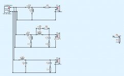


Project pics
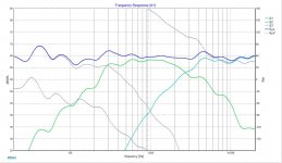
Enclosure, Measurements at 1mt (microphone always at tweeter level), and xover design.
Good work, @mikeoddone ! 😎😎😎
A+!
Could be wrong but I suspect the bump at 4500hz is from your woofer. Have you considered a steeper slope or notching it out? Looks like it could be a pain for analytical work.
Nah, it's the tweeter. Maybe some summing from the ring radiator and diffraction signals from the enclosure edge (plus that from the edge of the midrange cone).
The data sheet shows a 5db on axis peak at 4500db. https://www.eton-gmbh.com/fileadmin...Datenblaetter/SYMPHONY_II_5-312_C8_25_HEX.pdf
Care to elaborate on why you don’t think it’s an issue?
Care to elaborate on why you don’t think it’s an issue?
Sure. The woofer is 40dB down already at 2,3k. For the sake of the cause, add some 10dB for the -almost- octave to 4500Hz. That is -50dB. A peak of +5dB would turn out to be -45dB. That adds up to a staggering 0,05dB to the reference level.The data sheet shows a 5db on axis peak at 4500db. https://www.eton-gmbh.com/fileadmin...Datenblaetter/SYMPHONY_II_5-312_C8_25_HEX.pdf
Care to elaborate on why you don’t think it’s an issue?
I´believe it´s a little bit of different phenomenas
- midrange bump at breakup
- tweeter rta at enclosure. Actually it respects pretty well what shown the manufacturers datasheet. But showing that diffraction bump that kills tweeter smoothness at that critical area.
Is there any way I could make it better with the xo?
What would you guys try here? Should I change a little the enclosure front design?
If it is diffraction bump it is not fixable in crossover since the effect is different to different angles, acoustic problem. If driver datasheets show peak there just cut it with the crossover. Yes you could equalize diffraction on listening axis as well but it gets worse on any other axis. Diffraction related interference can be helped adding slants or roundovers side of the tweeter. The more there is flat baffle around drivers the more diffraction interference is my rule of thumb 🙂 Minimize empty baffle area anyway you can, roundovers being the best option.
You can test if it is diffraction that causes the peak if you do off-axis measurements or model the baffle in some diffraction simulator. The baffle seems so wide the biggest diffraction ripple should be a lot lower in frequency (< 1kHz, seems to be big baffle) right above baffle step frequency and any diffraction ripple higher than that (like at 4.5kHz) is usually smaller in amplitude. Hope it helps 🙂
You can test if it is diffraction that causes the peak if you do off-axis measurements or model the baffle in some diffraction simulator. The baffle seems so wide the biggest diffraction ripple should be a lot lower in frequency (< 1kHz, seems to be big baffle) right above baffle step frequency and any diffraction ripple higher than that (like at 4.5kHz) is usually smaller in amplitude. Hope it helps 🙂
My guess is: the tweeter center is about 8cm from the top edge. Likewise with the cone edge of the midrange. 8cm equals 4300Hz. That 6500Hz dip-ish curve could well be the cancellation dip from the same virtual sources. But the midrange bump could play along here.
I meant the mid range, not the woofer. My mistake. It is only down about 10 db. Easy to test. Disconnect the mid and see if it’s still there.
That makes sense. Since the cone resonance comes in at 5 to 6kHz, I’d choose a steeper typology (elliptical?) for the mid lowpass.
You could try a 1 ohm resistor on the tweeter coil, and see if it damps the response. If it does not, then tanking the mid will help.
Wolf
Wolf
- Home
- Loudspeakers
- Multi-Way
- 3way Studio Design