Actually, the software is assuming all cylinders (axisymmetrical). For bass reflex box internal volume, you can do any shape you want as soon as you keep the volume. As long as you do not create smaller resonant cavities (like connecting two larger volumes with a pipe. I have not so much experience with port location, but it looks like any position is actually used (and in theory it should not matter much - as long as it is not restricted e.g. by wall proximity).
I would not be too concerned about the port shape as long as it has a constant area and it is not too flattish. The best way to tune a bass reflex IMHO is measurement, so printing a prototype is a good idea - just be careful - the volume of the port does not count to box volume - so you must exclude it. I am maybe just a slightly advanced beginner, there are much more experienced guys here. I usually simulate to get a rough idea, build and then tune. Most of the things end as prototypes anyway🙂
I would not be too concerned about the port shape as long as it has a constant area and it is not too flattish. The best way to tune a bass reflex IMHO is measurement, so printing a prototype is a good idea - just be careful - the volume of the port does not count to box volume - so you must exclude it. I am maybe just a slightly advanced beginner, there are much more experienced guys here. I usually simulate to get a rough idea, build and then tune. Most of the things end as prototypes anyway🙂
So, to quantify things a bit - looking at the plans, the micro Fonken has a 2,1l main volume[/quote=
The original µFonken is 2 litres, the newer µFonkenSET and µFonkenPlus are 2.5 litre. The original was for FF85k and adapted for the F85wk. The newer driver also fit the larger enclosure for a bit more bottom.
The vent is the entire length/width with a spacer(s) to decrease vent area to the appropriate amount needed for the particular driver in the box. The same boxes fot the FF85wk, Alpair 5/2/3 or CHN50) and the Faital Pro.
Which other parameters are to be taken into consideration when building one?
The box volume and the vent area/length are the tuning parametres. With the miniOnken alignment the high aspect ratio of the vent also plays a role in the alignment. This does not show in a sim and i look for a specific shape of curve. I adjust volume and tuning until i get the shape i want.
What freedoms are there to remix?
Shape. The actual vent geometry plays a role, but that has to sort of been felt out by experience. For minimum (external) diffraction affects a teardrop like shape has been shown to be VERY good.

Is the ratio in which the two sub-volumes are divided by the insert of importance?
The insert is a brace. It has nothing to do with the tuning. It braces both the box, pushing (potential) box wall resonances up in frequency where they are unlikely to be excited, and it distributes the reactive energy of the driver across more box material.
dave
Looking at the pictures - the µFonkenSET seems best suited to printing. Is this a proprietary / monetarized design or are the measurements (to have a guideline to start with) availiable somewhere ?
Syncronistically the enclosure design i am most proud of. The looks on people’s faces when they hear them in the big system and they cannot believe what is coming out of those tiny boxes.
The µFonken is a free plan, the full planset with the trapezoids, and the plus enclosure as well as helper woofer/stands is a paid set of plans.
planet10-hifi miniOnken Plan-Set Subscriptions
But apart from ´remixing´ an existing design and to come back to the original question - given these popular drivers, are there successfull parameters to design a box around these seemingly popular drivers, or is it indeed best to stick with an existing design and perhaps modify it ?
You should start playing with a modeler and look to see what how changing things affect response.
Existing designs tend to be safer if they come from an experienced source. Tweaking them is certainly not an issue and adding creativity to the extant designs would be encouraged.
Is there risk by turning a proven cuboid design and turning it into another shape while keeping the volume and port dimensions ?
Some, but it will not show in a sim.
For example, with any iniOnken planset there are 3 fairly standard syle boxes. The trapezoid as shown, a rectangular version that is easier to build but still has significant chamfers, anf the cuboid Classic Golden Ratio (approx 1.618:1:0.618 box dimension ratio).
As the (plan) shape changes to more closely resemble a teardrop, the diffraction signature od the box decreases, and the box will “disappear” to a greater extent. The full-on tear-drop shape would maximize this trend.
Good to hear that in a closed box, I can not make great mistakes.
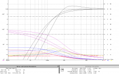
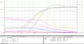
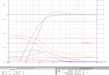
Sealed is very tolerant to differences unlike a reflex. But one does not get extention at the bottom so best used with a helper woofer. The difference in extention with these small drivers, is important as the vented boxes can reach the point where they have sufficient first harmonic reoroduction so as to give the apperance of low bass.
1.1 litre was sufggested as a sealed volume for the Fiatal, this should be considered the baer minimum, and as you can see fromt he sim, as you approach 50 litres the response improves.
Note: x axis in the Fitalgraph is out to 2k the others out to 1k so be careful comaring them). They all have F10 in the low-mid 80s.
The Faital is the best suited of the 3 for sealed. My use of the microSize box for it is a bit of a stretch.
dave
Attachments
Okay - since I could not get pre-calculated ´recipes´, I did what I initially wanted to avoid and played around a bit in software to do the calculations myself and ordered some drivers to play around.
I am printing a few pre-designed subwoofers at the moment (hexibase and zx82net), the goal is to design 2 pairs of speakers to go with (or that optionally could go alone).
Since I do not know if speakers with ports introduc drawbacks into the design or if I get the bass extension for ´free´, I will start with ported designs and see if I can manage. So my first try will be
A feasibility sample with inner walls printed well, but sounded ****/hollow - no idea if this was due to design, new driver or simply because it was alone without stereo partner. Next iteration will be a pair of the design below, guess I´ll see.


I am printing a few pre-designed subwoofers at the moment (hexibase and zx82net), the goal is to design 2 pairs of speakers to go with (or that optionally could go alone).
Since I do not know if speakers with ports introduc drawbacks into the design or if I get the bass extension for ´free´, I will start with ported designs and see if I can manage. So my first try will be
- A Monacor SPX-31M
- A 2,3l enclosure with rounded and trapezoid side walls (non-parallel top-bottom seems not so important due to the port being in the way, but could be added)
- A port tuned to 78 Hz (or so I hope, no idea really how the heavy flares affect everything), which can be easily replaced in case it sounds bad.
- As bonus, I will try to print no inner walls to gain a rougher surface
- Second bonus - it will have interchangeable side panels to be printed out of nicer filament that is too expensive to print the body out of.
A feasibility sample with inner walls printed well, but sounded ****/hollow - no idea if this was due to design, new driver or simply because it was alone without stereo partner. Next iteration will be a pair of the design below, guess I´ll see.
Attachments
Last edited:
Enclosure printed quite well - but I don´t like the decorative side panels. They do not print too well being quite thin and are too much hassle.
So I will go for version 2, this time with
Wondering if I should make the walls somewhat thicker, don´t know. But as it is, it´s at 1kg material (=10€) and prints in 3 days, quite nice.
If there are any caveats or suggestions, please let me know

Edit : just an image of version 1:

So I will go for version 2, this time with
- 3l interior volume
- 12mm walls
- non-parallel top/bottom walls
- some non-parallel interior structures to stiffen side walls a bit and help reduce wall reflections / center infill
- Some structure at the front to hide usually not-too-well-printing top layer
Wondering if I should make the walls somewhat thicker, don´t know. But as it is, it´s at 1kg material (=10€) and prints in 3 days, quite nice.
If there are any caveats or suggestions, please let me know
Edit : just an image of version 1:
Last edited:
Thanks pelanj - good to hear I do not seem to be on a totally wrong course 🙂
I hope it´s okay to adress your remarks with some further questions:
I tried to address the issue of sharp corners in general by
would you think this is sufficient or would more ´roundness´ be advisable ?
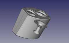
(image showing the corner between rear and side wall with the interior stiffening structures)

You seem to imply that the front baffle is of greater importance concerning sharp corners.
Since this models is planned to print with the front baffle up, I have to include support structures (which are quite steep and won´t print nice, but non-nice interior is acceptable to me). Could these already do what you had in mind, or would you build them more massive (without the cutouts) at the expense of interior volume ?
(image shows front baffle from the inside)

I hope it´s okay to adress your remarks with some further questions:
I tried to address the issue of sharp corners in general by
- having all interior corners rounded by 4mm
- printing without interior walls, which considerably roughens everything up on a scale of ~few mm (see image)
would you think this is sufficient or would more ´roundness´ be advisable ?
(image showing the corner between rear and side wall with the interior stiffening structures)
You seem to imply that the front baffle is of greater importance concerning sharp corners.
Since this models is planned to print with the front baffle up, I have to include support structures (which are quite steep and won´t print nice, but non-nice interior is acceptable to me). Could these already do what you had in mind, or would you build them more massive (without the cutouts) at the expense of interior volume ?
(image shows front baffle from the inside)
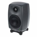
Yes, it is the exterior of the front baffle that would benefit from roundovers. Edges mean diffraction and that brings frequency response dips and peaks. The rings for the driver and port should have also positive influence. And as a last thing, since it is a full range speaker, its beaming may reduce the diffraction effect. This is hard to guess, it would need exact simulations or measurements. Try to look up some Genelec monitors - to get some inspiration on how to make roundovers.
Inside, the worse (more irregular) the inside, the better.
Inside, the worse (more irregular) the inside, the better.
Oh, I was not aware that you meant the outside of the front baffle - interesting, I did not realize this had an effect.
I already constructed some features on the front (more for aesthetic reasons, inspired by some cheaper Behringer monitors of mine with a look quite ´inspired´ by Genelec) which seem to go in the direction you mentioned. Could this suffice / is this what you meant with roundover ? At the moment, I do not plan to use front rings like in v1 - they would not match well optically to these roundovers (?).
(they are quite shallow, 3,5mm deep. The driver sits flush in the 2mm recess)

If I see correctly, there are sharp edges in the 3D model - see this small Genelec monitor - all is nice, smooth and round - and that is alo my cosmetic preference.
In this size class, the look is more important. Your design reminds me 90's plastic front speakers - and I have a weak spot for these too🙂
In this size class, the look is more important. Your design reminds me 90's plastic front speakers - and I have a weak spot for these too🙂
Attachments
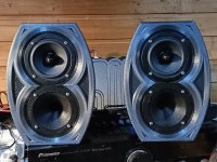
Ehy, that's a tweeter! No hole, ah-ha!
The guys at genelec really know how to impress people. A hole is nothing, it's a hole...a tweeter has radiating properties pertaining to the high frequencies, a hole reflects the redundancy of bass.
🤔
The guys at genelec really know how to impress people. A hole is nothing, it's a hole...a tweeter has radiating properties pertaining to the high frequencies, a hole reflects the redundancy of bass.
🤔
It's well known that the duct has to be in the vicinity of the speaker - not a problem with 2-3l boxesI have not so much experience with port location, but it looks like any position is actually used (and in theory it should not matter much - as long as it is not restricted e.g. by wall proximity).
I would not be too concerned
Uh... I've never done like that, but I keep reading all over the world peoples are enjoying doing that and suggest it as the right way of doing itI hope me asking a question on how to avoid gaining audio knowledge is not too un-fanatic, and it is not meant to would like to bypass all the knowledge-intensive parts (measuring a driver, simulating it with different volumes and designs, evaluating response curves and deciding which one corresponds to ´nice´sound ..... ), if at all possible.
I suggest only to add mass inside, like 1-2 lead sheets. An enclosure 1st needs to enclose... If it's transparent...
I hope me asking a question on how to avoid gaining audio knowledge is not too un-fanatic, and it is not meant to belittle your (frighteningly complex) hobby.
So.
I like 3D printing.
And I would like to play around with different (smallish, because of build volume restrictions) enclosure designs until I find the nicest one for my home.
And I would like to do this without getting into yet another hobby, if at all possible ( ... at least I can try). So I would like to bypass all the knowledge-intensive parts (measuring a driver, simulating it with different volumes and designs, evaluating response curves and deciding which one corresponds to ´nice´sound ..... ), if at all possible.
So my question is :
Can an audio-fanatic distill its knowledge into a set of parameters that sufficiently describe an enclosure so that it will at least sound ´okay´?
I hope that something like the following is possible:
-> And whatever you do, you will get ´good enough´ sound down to soandso Hz.
- Take well-known driver a
- Put it in a volume x
- Put in a port of area y and length z
- make sure that no two walls are more than l cm apart and/or parallel to each other
This would allow me to happily try out shapes without fearing that it is utter nonsense from the beginning.
Would this be possible - or is enclosure design far too complex to be distilled down to a finite set of parameters like in my example ? And if yes, which parameters would be neccessary?
Thanks for your time !
i have no experience 3D printing but i do have some speaker building knowledge, though not when it comes to measurement or passive crossover design ... for my next project i am planning to use DSP crossovers and tune them by ear.
i also want to incorporate some 3D printed parts into this next project. i suggest you do the same.
that is i suggest you take an overall plywood box and 3D print only the parts that are difficult to realize in wood.
this will allow you to have a bigger speaker than your build volume allows for and that in turn will result in greater performance.
take some proven design that will typically involve a plywood box and plastic tweeter waveguide as well as plastic bass reflex ports and just 3D print the plastic parts. you can probably get some carpenter to build the wood parts for you if you can't do it yourself.
only time people ever downsize their speakers is when it's a portable setup and people get old and can't lift the old speaker anymore to get it to location ... otherwise you should always use the biggest speaker you can, just as you would always use the biggest TV screen.
as Vincent Teoh says no videophile ever goes to heaven wishing they had a smaller TV ... the same goes for speakers.
feel free to ask me any questions about speaker design so long as it's not about measurement or passive crossovers. i hope in turn i will be able to ask you some questions about 3D printing.
OK i have an even better idea for you - 3D Print just the front baffle.
look at this speaker for example:
https://jblpro.com/en-US/products/vtx-v25-ii
https://adn.harmanpro.com/product_a...096805/vtxv25-ii_front_nogrill_z_original.jpg
this is the most advanced loudspeaker system ever made. this is what powers all the music festivals where 100,000 people bleed from the ears. it features a plywood box with cast aluminum front baffle.
so you do a plywood ( or MDF ) box and 3D printed front baffle instead of cast aluminum.
the logic is simple - front baffle is mostly holes - holes are more efficiently made using additive manufacturing like 3D printing than by taking material and then cutting holes in it.
the JBL VTX speaker also integrates the bass reflex ports into the baffle directly and so can you with 3D printing. your 3D printed baffle would integrate the baffle itself, the tweeter waveguide and bass reflex ports all into a single piece.
you could separately 3D print some kind of a speaker grille ...
the rest of enclosure would just be rectangular pieces of plywood or MDF that Home Depot will actually cut for you themselves ! all you need is to glue them together. well, you would need to cut the hole for speaker wire terminals ... i'm sure any carpenter would cut those holes for you for 5 bucks if you can't do it yourself.
Well, this is a very interesting idea - with my currentl printer, enclusures of a few litres are feasible, but more does not really make sense and takes unreasonable amounts of time and plastic.
So, taking wood to build a primitive box and using 3dprint for parts where this provides a real benefit makes sense. Complex internal structures, ports, somesuch. WIll have to think about it. With 3D-printed joints, I could even avoid having to glue everything together and worry about corner finish. Hmmm.
Do you have something in mind ?
this is one possible example of a speaker:
in their case both front and back are some kind of composite or aluminum or whatever but you could do just the front.
in their case both front and back are some kind of composite or aluminum or whatever but you could do just the front.
- Home
- Design & Build
- Construction Tips
- 3D printing enclosures without actual knowledge