Why can’t the holes be accurately measured?
The holes can be accurately measured.
My point was that making a horn is easy; making the mounting plate is hard.
60 degrees Celsius for Wrinkle Paint and 85 degrees for PETG.PLA has a Glass Transition Temperature of about 55 to 60 deg C, so it will start to soften above that. PETG is 85.
I will add PETG to my printer order!
Do some research on how to print PETG and practice in PLA first as it is easier to print and get things dialled in. Most basic 3D printers need some to a lot of tuning to get them to print properly.
You might only want to print the waveguides but to make them good will take a bit of trial and error, unless you are willing to use prints that look like Patrick's 😀
You might only want to print the waveguides but to make them good will take a bit of trial and error, unless you are willing to use prints that look like Patrick's 😀
The most important thing to remember is that practice makes perfect. As basic as it may appear, the more you use blender, the more quickly you'll be able to set up scenarios and employ shortcuts. You'll also learn how to resolve any issues you encounter over time because you'll almost certainly encounter them again.I have no experience with heated paints on prints, but PLA will not do it. PETG maybe. There is a material, rPET, which you can buy at ekomb.cz, which is strong and durable, but not so easy for printing, it needs even higher temperatures than PETG and at least 0.6 mm nozzle. The overall mechanical strength will depend on print settings - in general, more perimeters and infill, higher temperature and no cooling fan produce stronger prints. For maximum strength, you need to print some test objects and make destructive tests. For example, my PLA prints with 5 perimeters and 30 % infill are very strong and require goid amount of force to do any damage. Also, you can make the walls thicker, add ribs, etc.
I also suggest memorising as many keyboard shortcuts as possible. Also, create shortcuts for the tasks you do most frequently. It really speeds up the process.
I also rarely use the "file," "edit," or "view" buttons at the top of the viewport, preferring instead to use F3 to get what I'm looking for. It seems faster to me, but it's probably up to you.
When it comes to modelling, aim to be as non-destructive as possible. That is, utilise as many modifiers as possible without adding verts in edit mode. It can be difficult to make modifications later if you have a large number of faces to deal with. Modifiers allow you to change things after they've already happened.
If you have any further questions, please let me know and I'll be pleased to assist you!

Great stuff. 'Support cubic' in prusa sl1c3r uses an adaptive cubic infill that uses higher density in areas that require more support. you can use it as a standard part infill (its normally used for supports). I plan to do some experiments with that.
3d printed metamaterials (custom inflls) for this is something I was dwelling on a couple weeks ago and then found Bill and now you have also been pondering this.
I will be playing with the carbon loaded PC filament too. its pricy, but very strong and I wonder if it might be able to come out not that much more than a high quality ASA when the smaller amount I might need is taken into account. proto in cheaper materials, then use that. perhaps will work out cheaper when time is factored in vs full on materials research and huge print times.
This filamentin bulk its significantly cheaper, but not cheap. but maybe cheap compared to elaborate and time consuming other methods of strengthening (which of course are not without merit), particularly with less used in supports. I would expect to be able to drastically reduce wall thickness. requires a higher temp hot end ~280C, preferably closed printer and ~80C on the bed.
Last edited:
This. So much this.When it comes to modelling, aim to be as non-destructive as possible.
Also, I tend to project as much geometry onto the model from sketches as possible too, to make those easier to edit and tie to editable dimensions.
Last edited:
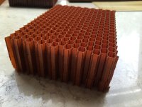
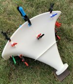
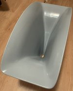
Someone asked me how I make my waveguides that have a semi-cylindrical mouth. So I'll show how to do that today.
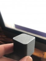
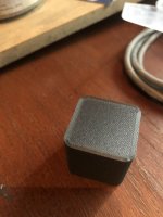
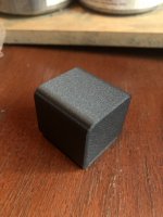
The attached pictures aren't my waveguides, but the idea is the same.
The attached pictures aren't my waveguides, but the idea is the same.
Attachments
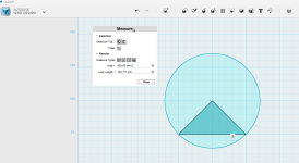
The first thing you start off with, is the arc that will define the semi-cylindrical shape of the mouth.
I personally like to use an arc that's 90 degrees. Speakers like the JBL 4367 and the Kali LP6 use an arc that's a narrower angle than that.
I like the bigger arc because it reduces the required width of the waveguide. You could use as much as a full 180 degrees, or as little as one degree, but I think 90 is a good compromise.
The reason that using an arc allows for a shorter width, is because the arc shape basically truncates the edges off of a "normal" (flat faced) waveguide.
IE, if you had a flat faced waveguide that measured 40cm wide by 20cm tall, if you used an arc for the mouth, you can get the same coverage angle with as little as 20-30cm of width. You basically reduce the width by about 30% or so. (A lot will depend on your roundover, vertical beamwidth, horizontal beamwidth, etc.
In the attached pic, I have an arc that spans 90 degrees that's 100mm wide. I will "scale it up" so that it's the width of my intended baffle.
Attachments
- Home
- Loudspeakers
- Multi-Way
- 3D Modeling Tips and Tricks