agent.5 said:
What is PP heating? I am pretty sure that VT127A has the same heater requirement as a 250tl. So you may as well add this big tube to your list.
hmm, sorry : PP configuration, not SE , and avoid DC rectification / filtering for heating : hum cancellation will be improved !
250tl , why not : if i had some left ... so many tubes, so little time
😀
Pierre
Some HK54 on my avatarkmaier said:Hi Coresta,
Sadly, I have no HK54 tubes.... but do have the spec sheet. These would also work well and as suggested earlier, would be a bump up. I'm also looking at the 35T from Eimac, looks like another upgrade option.
My main reason for adopting some of these older transmitting tubes (besides looking pretty when lit) is their price is still attractive and they should certainly have longer life than a 45 or 2A3. The market prices for 45s and 2A3s has shot up and the actual quality of the remaining tubes has shot down.
Are you also using your 3C24s in an audio amplifier?
Regards, KM
😉 Pierre
3C24 amplifier finished - WOW !!!
Friends
I finished my 3C24 SE class A2 tube amplifier.
The sound is fantastic, I love it !!!
See here:
http://www.youtube.com/watch?v=rcVQkrff6pM
And I play it in video with bad laboratory boxes...
It have a "300B sound" !!!
Aldovan

Friends
I finished my 3C24 SE class A2 tube amplifier.
The sound is fantastic, I love it !!!
See here:
http://www.youtube.com/watch?v=rcVQkrff6pM
And I play it in video with bad laboratory boxes...
It have a "300B sound" !!!
Aldovan
Nice to see some additional interest in the 3C24.....
Aldovan, nice looking amp... how about a description of the circuit (transformer-coupled to the grid)? Which iron did you use for outputs? I noticed the anodes do not appear to be glowing even red. According to some info posted by Michael Koster, this could result in reduced tube life as Eimac found that Tantalum acts as a getter when operated at higher temps. Certainly a good read from Michael's posted link.
Pierre, having access to a lathe is nice... you can turn your own heat-sinks. Maybe use copper? Better conductivity.... both electrical and thermal. Maybe get a HR-2 heat-sink as a pattern or perhaps Aldovan can make a measurement of his as they appear to be HR-2s from the You-tube clip. I'm still uncertain on running these with an AC filament (even push-pull). However, do post your findings on this once you get started on the design/prototype phase... very interested to hear about this.
Regards, KM
3C24 amplifier
KM
I do not use transformer coupling. My coupling circuit is totally different. I do not use the classic methods.
The tubes have a small red collor, because the polarization is about 12W, only.
Aldovan
KM
I do not use transformer coupling. My coupling circuit is totally different. I do not use the classic methods.
The tubes have a small red collor, because the polarization is about 12W, only.
Aldovan
Hi Aldovan,
That's interesting... what kind of power are you getting and what are the distortion levels? I would suggest reading the Eimac history on the tantalum tubes however.
Regards, KM
That's interesting... what kind of power are you getting and what are the distortion levels? I would suggest reading the Eimac history on the tantalum tubes however.
Regards, KM
Kim
Yes, you are correct, I will use a high dissipation.
The power is about 5 -6 W, is fine for my small room.
Aldovan
Yes, you are correct, I will use a high dissipation.
The power is about 5 -6 W, is fine for my small room.
Aldovan
Resistor question
Hi All
The two resistors on the heater /cathode inTossie's 3C24 design are not shown on the schematic . I have noticed that on some of his other dynamic coupled amps that he has put these resistors which are usually between 22 and 39 ohms on each leg of the heaters in conjunction with a pot . I can understand the basics of using a bypassed cathode resistor and the humbucking pot but don't understand what these resistors are for and the calulations for arriving at the values that he uses could some one please let me know .
Thanks
Nigel
True, the schematic shows the balance pot only. From the close-up pic, the resistors are in series with each pot leg. Basically I think he used some lower value pots to widen the null adjustment range and nothing more. I would suggest using a 100-ohm pot with padding resistors as shown in my earlier schematic, it works fine.
Regards, KM
Regards, KM
I have done that very thing on my big DH amp. It can run either 5V or 10V filaments, and I put 20R resistors in series with the pot when running the 10V types in order to cut down on the pot's dissipation.
cheers,
Douglas
cheers,
Douglas
Thanks KM and Douglas for your replies I had thought that may have been a bit more complicated as I haven't been able to find any information on this yet .
Nigel
Nigel
3C24 SE amplifier ...
Friends
I make modifications in the bias of my amplifier.
The plates work red, now.
See here:
http://www.youtube.com/watch?v=r8CQBtU_-Zc
Aldovan

Friends
I make modifications in the bias of my amplifier.
The plates work red, now.
See here:
http://www.youtube.com/watch?v=r8CQBtU_-Zc
Aldovan
Re: 3C24 SE amplifier ...
I'm just wondering how you can obtain both gain and drive with a single triode section or is your design using a hybrid driver ?
316A
I'm just wondering how you can obtain both gain and drive with a single triode section or is your design using a hybrid driver ?
316A
Re: Re: 3C24 SE amplifier ...
I'm just wondering if/when we are going to get to see the circuit. Sure it's pretty and all, but I for one would like to see some information ;-)
I guess it's a secret...
Michael
I'm just wondering if/when we are going to get to see the circuit. Sure it's pretty and all, but I for one would like to see some information ;-)
I guess it's a secret...
Michael
Re: Re: Re: 3C24 SE amplifier ...
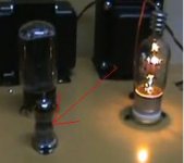
It shouldn't be , this is supposed to be a DIY . The driver looks like a 9 pin double triode , in the video there are two sets of heaters visible . Unless it's a cathode follower and the gain is coming from elsewhere or there is a mosfet under the chassis , I can't see how Aldovan is doing his design .
316A
Attachments
Re: Re: Re: Re: 3C24 SE amplifier ...
Well, I know how *I* would do it, which would only require a MOSFET as a mu-gyrator, would only require a modest triode like a 6072 for gain, assuming some local NFB. A power drive circuit would work with a 6072 also. I'm also interested in the output damping factor and if/how feedback is used. a 24K OPT would probably be OK but I'd be tempted to use local feedback.
Share...
"The plates work red, now."
Did you notice any change in sound with the new operating point?
3C24 amplifier
Friends
The circuit do not is secret, but I do not can show now, because I waiting the USA patent. The design is new and do not use mosfet or other semiconductor.
The driver is a 6N1P. The output transformer do not use negative feedback. The circuit is very simple and work fine, I do not like use semiconductor or complicated circuits.
My next amplifier will use a 15E triode in output.
Aldovan
Re: 3C24 amplifier
I see, it's not secret but you can't show it because it's your intellectual property. Well thanks for sharing as much as you can. Can I DIY it or not?

I see, it's not secret but you can't show it because it's your intellectual property. Well thanks for sharing as much as you can. Can I DIY it or not?
Aldovan, your design secrecy sounds intriguing... maybe someday you can share it, but your choice. I'm wondering if you're noticing an audible difference since increasing the plate current... or finding that the specifications of the amplifier have changed... anything?
Despite this being a DIY forum, nobody "has" to share their designs... that's a personal choice which includes showing pictures or even mentioning it. Some designs I've shared, others I won't... my choice. To each their own.
Regards, KM
Despite this being a DIY forum, nobody "has" to share their designs... that's a personal choice which includes showing pictures or even mentioning it. Some designs I've shared, others I won't... my choice. To each their own.
Regards, KM
Some designs I've shared, others I won't... my choice. To each their own.
I post all of my designs, and ideas whether they are tested and proven or just dreams. The hope is that someone out there can make them work better than me. This is a real possibility since I am limited by an ever shrinking budget.
After 5 years of trying I have come to the conclusion that I will never make any real money in audio. This has been explained to me several times by those who have gone before me, but yet I try any way. I have however managed to figure out how not to lose money.
You want to make money in audio, sell $1000 cables, stones, or a new magic device. Patented circuits won't do it. I didn't believe this 5 years ago, but now I do. I have decided that breaking even is OK as long as I still have my full time engineering job..... designing patented circuits!
This year I have ventured far far from my usual SE DHT's and I am finally listening to a 80W P-P amp that I like. The schematics and the design details from the initial idea to the finished amp are unfolding here are on this forum.
http://www.diyaudio.com/forums/showthread.php?s=&threadid=133034&highlight=
- Status
- Not open for further replies.
- Home
- Amplifiers
- Tubes / Valves
- 3C24SE amp...