This is one of the amps. Built on an Eico HF-20 chassis and using the original Chicago output transformer. In their current form, they will be 20 years old in 2020.

This discussion, and the various vaporizing anecdotes, certainly suggest that eye protection
is a must when working on this type of power supply.
It should always be used in any sort of bench work as well.
This is one of the amps. Built on an Eico HF–20 chassis and using the original Chicago output transformer. In their current form, they will be 20 years old in 2020.
So where are the 3000 µF ÷ 500 V cans? I don't see 'em. Anywhere. And they would be conspicuous.
Just saying,
GoatGuy ✓
They are in the chassis beneath the power transformer. Very, very tight fit. The tops of the caps, SS rectifiers and wiring is in the back and essentially inaccessible without removing the caps.
Here's the thing… and this will sound like a kazoo in a concert hall, but:
A 3,000 µF … 500 V power supply final capacitor is just absurdist overshooting of the need to “solve a problem”, namely, power supply ripple.
First and foremost, a string of LC or RC low-pass filtering stages can accomplish remarkably low ripple, in only 3 stages. The L's don't need to be ridiculous, the C's don't need to be kilo-micro-farad monsters.
They don't.
Even if there is some droop in the power during exciting bass transients, the effect of GNFB is going to mask almost all gain-loss on output. Especially if the beam pentodes' screen grids are using the ultralinear-tap-on-output-transformer-primary as their regulation source.
Thing is, you really don't need such an 8 gauge shotgun sitting in a power supply. (Look 'em up … Uncle had one. You wouldn't believe the cartridges, the kick, the kablooey).
Anyway,
Just saying,
GoatGuy ✓
At the time, I was trying to minimize B+ sag. I didn't care about ripple, except that it had to be low enough to be safely within the specs of the caps. The driver is LM317 regulated, so there is plenty of ripple rejection. No ultralinear on these. Voltage regulated screens again on the same Maida LM317 VR. But the B+ would need to sag below the regulated voltage, which is not going to happen with reasonably sized caps. I've done the driver/screen volt reg on Stereo 70s with the updated PS caps. Works great. Sounds like they have twice the power.
Last edited:
Did you ever measure the actual sag with a worst-case test signal, and compare the deviation and rebound to the ripple waveform?
They look like very closely spaced 807's. Unless you are pushing them in to AB2, the signal related power supply current swing isn't going to be substantial.
They look like very closely spaced 807's. Unless you are pushing them in to AB2, the signal related power supply current swing isn't going to be substantial.
Here's the thing… and this will sound like a kazoo in a concert hall, but:
A 3,000 µF … 500 V power supply final capacitor is just absurdist overshooting of the need to “solve a problem”, namely, power supply ripple.
First and foremost, a string of LC or RC low-pass filtering stages can accomplish remarkably low ripple, in only 3 stages. The L's don't need to be ridiculous, the C's don't need to be kilo-micro-farad monsters.
They don't.
Even if there is some droop in the power during exciting bass transients, the effect of GNFB is going to mask almost all gain-loss on output. Especially if the beam pentodes' screen grids are using the ultralinear-tap-on-output-transformer-primary as their regulation source.
Thing is, you really don't need such an 8 gauge shotgun sitting in a power supply. (Look 'em up … Uncle had one. You wouldn't believe the cartridges, the kick, the kablooey).
Anyway,
Just saying,
GoatGuy ✓
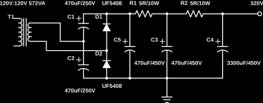
I use 3300uF in my monobloc supply. The amp idles at 500mA, 300V. It peaks about 1.5A. What would you change in my power supply to eliminate the "8 GA shotgun" and still deliver the current?
Attachments
Hello,
Dont you have two nice surplus? chokes lying around to turn one of the RC into an LC network?
Greetings, Eduard
P.s i do but sending them to Canada would cost a leg
Dont you have two nice surplus? chokes lying around to turn one of the RC into an LC network?
Greetings, Eduard
P.s i do but sending them to Canada would cost a leg
final capacitor is just absurdist overshooting of the need to “solve a problem”, namely, power supply ripple..... there is some droop in the power during exciting bass transients
I didn't realize from the early posts that this was an 807 amp.
I have fitted some fat caps into the power supplies in some of my push pull amps, and will likely do the same in those I build in the near future. Ripple is not the reason. A certain amount of energy storage in the power supply of an amp is useful for feeding the big transient currents that an amp can see when driving a speaker with real music.
The peak current seen in an amp can be determined by load seen by the tubes, and the B+ voltage. Many assume that a 5,000 ohm OPT will present a 1250 ohm load to each tube in a P-P amp.
This is true with pure sine waves into a resistive load. When the bass is pushing the speaker cone one direction and a transient drum hit tries to instantly reverse it's direction, the dynamic impedance presented to the output tube can be quite low. I usually assume that the peak current can be whatever the output tube's cathode can supply.
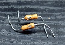
I know from my testing that a pair of 6L6GA's (same guts as an 807) can stuff about 100 watts of continuous sine wave power into a 3300 ohm OPT running well into AB2 before a tube arc spoils the fun. Two different arcs occurred, both in the 110 to 120 watt range, neither were fatal to the tube, but both caused the 1 ohm 2 watt cathode current sense resistor to scatter its guts. Yes, the monster HP power supply was used to feed this. This is a peak current in the 450 to 500 mA range.
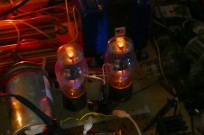
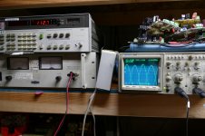
The pictures show the scattered resistors, the tubes not glowing at 112 watts output, and the test equipment at the 112.7 watt moment. The scope shows the plate voltages on each tube, the audio analyzer shows 112.7 watts out, and the power supply shows 500 volts and about 700 mA (two channels running,and about 50 mA goes to the driver boards). "Stuff happened" when I turned up the drive a bit more. I changed out the blown resistor and re-ran the test with the same tubes. This time the resistor blew in the other channel.
don't need such an 8 gauge shotgun sitting in a power supply......Unless you are pushing them in to AB2
Even my snake hating neighbor uses a 20 gauge shotgun to blast snakes!
Even in AB2, I would tend to use a "normal sized" electrolytic 100 or so uF with a 100 uF or so polypropylene motor RUN (not START) cap in parallel.
The motor run caps are designed to run continuously from the AC line, eating all the transients that come it's way and introduce a phase shift for an AC motor, all while carrying a current in the tens of AMPS. These have a very low ESR and ESL which is just what's needed to feed the peak currents in a big tube amp. Adding such a cap to the power supply in my SSE amp has become the most popular user upgrade. Many users report better dynamics, and this is an SE amp.
Some of the largest TV sweep tubes have a peak current rating of 1.4 AMPS. For several of these in parallel, a 12 gauge might be appropriate....two motor run caps.
Attachments
All this talk about exploding things...
Quite some time ago I had a 4 microfarad cap charged to some 3000 V and I wanted to discharge it, for safety. I had a 22 M resistor and thougt the rating was sufficient, but it went bang and took off a part of my nail. I didn't know resistors had voltage ratings too.
Quite some time ago I had a 4 microfarad cap charged to some 3000 V and I wanted to discharge it, for safety. I had a 22 M resistor and thougt the rating was sufficient, but it went bang and took off a part of my nail. I didn't know resistors had voltage ratings too.
I use 3300 µF in my monobloc supply. The amp idles at 500 mA, 300 V. It peaks about 1.5 A. What would you change in my power supply to eliminate the "8 GA shotgun" and still deliver the current?
Well … OK.
As I understand it, that voltage-doubling rectification is somewhere between non-doubling half-wave and non-doubling full-wave in terms of raw first-capacitor-stack ripple.
I modded my CLCLC algorithm to handle it. Used L values of 0.001 H to sim “no real inductance” effect. Used your 5 Ω resistors. Used C₁ as 235 + 470 = 705 µF. C₂ as 470 µF. C₃ as 3000 µF.
The results are attached. I didn't sim 1500 mA peaks. I suppose I could. Not that hard to do. The sim starts with 100 mA load or so , then jumps to 500 mA. To see LCRC response.
I'll try other values, less 8 gauge shotgun level, yet still satisfying the low droop, low ripple requirement.
GoatGuy
Attachments
Hello,
I attach some welding wire to both terminals and put it on my covered private balcony and let one of the neighbourhood cats which are always trespassing take care of it.
But i never had a cap charged with more than 800 volts.
Greetings, eduard
I attach some welding wire to both terminals and put it on my covered private balcony and let one of the neighbourhood cats which are always trespassing take care of it.
But i never had a cap charged with more than 800 volts.
Greetings, eduard
I am using Russian version of 6BG6G at 20mA idle current. Love these tubes. Have a large stockpile. NI 10W heat sink chassis mount 1 ohm cathode resistors for reliability and thermal stability. I have several polyp motor caps in my stash. Need to give them another try. I previously lived in LA area and with Apex and the TRW swap meet, tons of mil spec parts for DIY. I miss that.
I use 3300 µF…
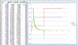
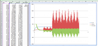
Now … new and improved … with '1500 mA spike loading'.
Created a spikey_load( i_mean, sec_delay ); function to turn on after 1 second, then have a non-harmonic quadruple sine wave load of
2 units of 44 Hz
1 unit of 77 Hz
1 unit of 190 Hz
½ unit of 250 Hz
The sines are raised to the 7th power.
This preserves their sign (even powers result in all-positive, right?) They're added together in the ratios shown. To that is added a ±½ (range) random element too. Just to further “mess up” the load.
Like real music source material.
Again, applied it and herein are the pair of diagrams.
Remarkable how a powerful spikey load influences the “net ripple”.
Just saying,
GoatGuy ✓
PS: do remember that the ripple is in millivolts on the graph, not volts. So, it is still small.
Attachments

Last edited:
Hello,
Dont you have two nice surplus? chokes lying around to turn one of the RC into an LC network?
Greetings, Eduard
P.s i do but sending them to Canada would cost a leg
They would have a higher DCR than 5R...
Now … new and improved … with '1500 mA spike loading'.
Created a spikey_load( i_mean, sec_delay ); function to turn on after 1 second, then have a non-harmonic quadruple sine wave load of
2 units of 44 Hz
1 unit of 77 Hz
1 unit of 190 Hz
½ unit of 250 Hz
The sines are raised to the 7th power.
This preserves their sign (even powers result in all-positive, right?) They're added together in the ratios shown. To that is added a ±½ (range) random element too. Just to further “mess up” the load.
Like real music source material.
Again, applied it and herein are the pair of diagrams.
Remarkable how a powerful spikey load influences the “net ripple”.
Just saying,
GoatGuy ✓
PS: do remember that the ripple is in millivolts on the graph, not volts. So, it is still small.
Pretty cool 🙂 I have no idea how to do that kind of programming 🙂 I can hardly get my bash scripts to work properly haha
All this talk about exploding things…
Quite some time ago I had a 4 µF cap charged to some 3000 V and I wanted to discharge it, for safety. I had a 22 MΩ resistor and thougt the rating was sufficient, but it went bang and took off a part of my nail. I didn't know resistors had voltage ratings too.
Yes, they do. The real problem with really high value resistors and high voltages is that even when the resistance 'winding' fails, the high voltage tends to happily jump right across the newly-made gap. At first lowering the resistance (loss of material), then further doing so as the arc eats up more and more. Soon, the arc just does and end-run and jumps the shark. Then the resistor isn't much of a resistor any more.
Personally, I have found that strings of the very old fashioned, used-to-be-common carbon composition resistors with 2.2 MΩ values are good. Oh, there are some really cool glass encapsulated hermetic hi-volt resistors with long ceramic forms and sputtered-on spirals of high resistance ceramic stuff … inside a sulfur hexachloride gas atmosphere to suppress arcs … but those are darn expensive. Thirty bucks and up.
Making a chain of 2.2 MΩ resistors at maybe 5¢/ea is the way to go. Just remember to 'shrink seal' the chain in multiple layers of heat-shrink tubing. Like 5 layers. Then you're good to 20 kV or so. (you'll smile… I also include a couple of appropriately trimmed bamboo skewers before the heat-shrink, to make the whole affair quite stiff.
Indeed … Using a couple of 'standard multimeter probes' and piece of RG–59 cable, one can solder 10 of the resistors in a very short chain, tapping the last one as a 10:1 voltage divider, and wrap the whole kit in the stripped-back braid and insulation. Shrink wrap the whole sucker, and you've got quite a safe hi-volt bleeder, as well as decent way to measure its voltage using non-exotic multimeters.
Obviously, choosing other ratios for the final resistor allows for 100:1 or even higher attenuation. Especially for metrology. Using a chain of 10 ea 22 MΩ resistors and one 220 kΩ as the 1000-to-1 voltage divider is how I made my 'high volt metrology probe'. Very safe, too.
Presents 220 MΩ load to the measured-device. Likewise, delivers 220 kΩ impedance signal to the multimeter or oscilloscope. 30 kV becomes 30 volts. Perfect for the (ahem, ah..., err...) now-obsolete high-volt giant-screen CRTs that once graced nearly all homes in America and Europe.
Just saying,
GoatGuy ✓
Hello GoatGuy,
What program are you using for the PS simulations? I would like to perform precise simulations; a 5.56 NATO approach rather than my punt gun method. Transformer has 700VCT 145mA plate winding.
Thank you.
What program are you using for the PS simulations? I would like to perform precise simulations; a 5.56 NATO approach rather than my punt gun method. Transformer has 700VCT 145mA plate winding.
Thank you.
High energy storage PSUs should have interlocks to prevent accidental contact. Alternatively, use real engineering to eliminate them where they are not needed.
- Status
- Not open for further replies.
- Home
- Amplifiers
- Tubes / Valves
- 375 Joules PS for my monoblock tube amps