You can't say that. Pentode gain depends on transconductance and plate load.You're right, the 310 has more gain than I remembered.
5842 is on (over) the limit of grid voltage.
A good option is C3g in triode, mu of 40, enough current to drive 300B grid, preferably choke/capacitor or interstage transformer coupled.
Well, I was referring to the use of the 310/6SJ7 in that particular circuit. In other words, that particular amp has more input sensitivity than I recalled. The OP is looking for lower input sensitivity.
Type 6EJ7/EF184/Russian 6Zh51Pi makes an excellent triode with a mu about 50. Lots around now, but probably not forever.
All good fortune,
Chris
All good fortune,
Chris

Now we are getting warmer...EF184
But - the EF184 does not measure very well, and in any case will struggle with 2V rms input voltage (2.8V zero→peak) without modifications.
But other mid-to-high gm TV IF pentodes make seriously good 300B drivers.
No need to run them in triode mode (large Miller effect loads the source).
In pentode they give excellent results, and the high gm can be used for linearisation: either with G1 feedback, or simly by degenerating the cathode.
Design Example:
300B with normal biasing: -71V
Input voltage 2V rms = 2.8V zero→peak
Required gain = ca. 25
Choose easy to buy driver valve:
EF80 is a common IF pentode, and you can still buy Mullard military ones for the price of a London pint.
And with many similar types for substitution.
suitable operating point (data sheet recommendation):
Va = ca. 200V; VG2 = 200V; Rk = 200Ω; Ia = 10mA nominal; IG2 = 2.6mA; S = 7.1mA/V
Linearise the transfer function and reduce the gain to the design value:
Ra = 9.1kΩ
S = 7.1mA/V (bypassed); with all of the 200Ω Rk left unbypassed, the effective gm falls to 2.93
GAIN = gm * Ra = 26.7; (use a slightly lower or higher Ra to fine tune the gain, if desired)
Bonus: The unbypassed Rk also allow the input voltage to be greater than the driver's bias voltage, without overload..
Well-designed pentode drivers sound better than run-of-the-mill triode designs as Western Electric must have known.
The woolly-sounding 6SN7 2-stage is definitely to be avoided.
http://www.klausmobile.narod.ru/testerfiles/6j51p.htm
Although there's nothing wrong with pentodes. Also 6Zh9Pi and 6Zh11Pi families.
All good fortune,
Chris
Although there's nothing wrong with pentodes. Also 6Zh9Pi and 6Zh11Pi families.
All good fortune,
Chris
The high-gm ones can be used too, but typically they need more linearisation, and they prefer 150V operation.
An ECC88 / 6DJ8 driver tube with a suitable interstage transformer will nicely drive a 300B according to your needs. The interstage also prevents DC blocking distortion ("farting out").
See here for an example: https://www.homebuilthifi.com/project/462
See here for an example: https://www.homebuilthifi.com/project/462
Another benefit of tailoring the gain of the driver to the maximumm input voltage: it's unlikely to try to drive the 300B grid positive. And in my design suggestion, the driver Ra value will limit the charging current to the capacitor, even if there are small overdrive events.
Of course, IT coupling is very nice, but much higher cost than such a simple RC-coupled pentode.
Of course, IT coupling is very nice, but much higher cost than such a simple RC-coupled pentode.
What I can’t understand is the approach of the problemOh boy... 😆 , thanks for spotting.
E88C seems to be unobtainium as well. So I would need to use a diff one if I opted for the SRPP variant.
With the circuit I sent you can find a good gain, good linearity ( not as ecc88) reasonable low Zout
And it is tested !
And the E88C is not so expensive compared with some others
In addition you can try the mu follower configuration checking carefully the bias point
The EF184 is good as triode with 55 of gain ( theory) and 5k5 ohm of Rp but the Cin in not low
The E280F is also good but expensive
Ec8010 is good
Ec8020 the best
Walter
I usually use D3a/E280F/E810F/E180F or C3g/C3m/(rare)C3o trioded pentode as VAS stage.
One of the simplest architecture:

The pentode replaceable with any good high gm pentodes listed above.
The VAS stage linearity can be increased if you use choke/interstage or active (CCS, gyrator) loading.
My favorite is CCS loaded D3a or C3g stage.
One of the simplest architecture:
The pentode replaceable with any good high gm pentodes listed above.
The VAS stage linearity can be increased if you use choke/interstage or active (CCS, gyrator) loading.
My favorite is CCS loaded D3a or C3g stage.
"C3g will provide that."
No, C3g (as many high Gm pentode) gain also "too much". The LTSpice voltage source is peek, so 2.08V peek is 1.47V RMS.
If the OP insist on using 2V RMS as maximum input, need to perfectly construct power stage (B+, bias, operating point), before VAS stage development begins.
If the perfect (fixed value) bias voltage is available, arbitrary driver may be sufficient, which gain is equal, or higher than expected.
If the 2V RMS input (as fixation) cannot be changed, simple resistive divider helps.
Even C3g is not guaranteed to have enough headroom: consider the tolerance of Ia on the cathode voltage; Rk might need to be select-on-test.
Some triode designs will need cut-and-try value changes to set the gain at the design value of x25-26 (28dB) for the nominal 300B bias of -71V.
Meanwhile, a pentode stage (with unbypassed cathode resistor Rk) can have more headroom, more linearisation, and a free gain selection without concern for the relationship between Ra and Rk & ra.
Last edited:
I don't see a "2.08Vpk voltage source"; C3g cathode is at 3V so the grid can accept 6Vpk-pk which is perfect for 2VRMS.The LTSpice voltage source is peek, so 2.08V peek is 1.47V RMS.
This is in line with my experience for C3g in triode as input/driver for a two stage amplifier with 180V anode and 15mA current.
In case of choke or interstage transformer loading the mu of 40 will also be the voltage gain.
300B grid requiring ~ 50VRMS will be perfectly driven by a C3g triode stage.
@Rod: the x number of Siemens NOS C3g's I used as input/driver were very stable w.r.t transconductance a.s.o. so they biased perfectly. Headroom with inductive loading is not an issue as you will know. Agree that a well designed pentode stage is a good option as well.
What I can’t understand is the approach of the problem
With the circuit I sent you can find a good gain, good linearity ( not as ecc88) reasonable low Zout
And it is tested !
Using the the E88CC was a mistake by me, because I did not read carefully enough to recognize the missing C. If at all possible, I typically try to simulate to get an impression and to be able to compare, since it is not possible to build all possible options 🙂 .
And the E88C is not so expensive compared with some others
I have now found one good source for the E88C. Indeed it is pretty inexpensive. When I wrote "unobtainium" yesterday, I hadn't been able to find any shop I could buy them.
In addition you can try the mu follower configuration checking carefully the bias point
The EF184 is good as triode with 55 of gain ( theory) and 5k5 ohm of Rp but the Cin in not low
The E280F is also good but expensive
Ec8010 is good
Ec8020 the best
I will not be able to design a driver stage myself. That is why I asked for schematics having a sensitivity matching my system well.
What about RF triodes or triode-wired RF pentodes with mu of about 35 to 40?
5842
6S3P-EV
12GN7A-triode
6J9P-triode
6e5P-triode
Thanks, but being a somewhat educated layman only, unfortunately I can not design an amp myself...
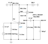
Here is yet another solution, posted here on DIY a while back
It was meant to drive a 2A3 I recall, the 100 pF load was intended to simulate the 2A3 Miller effect.
Many will reject it since it uses a pentode as a voltage amplifier. Pity! 😀
It was meant to drive a 2A3 I recall, the 100 pF load was intended to simulate the 2A3 Miller effect.
Many will reject it since it uses a pentode as a voltage amplifier. Pity! 😀
Attachments
Weather was really bad here and I had lots of time hammering spice...
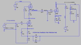
I might have found a simple driver meeting my requirements. The circuit has a sensitivity of about 2.2Vpp, so has some headroom too. Can you experts confirm this should work fine? And maybe check my 6DJ8/6922/E88CC setup if it needs to be improved / corrected? According to LTSpice it looks OK, but who knows? Any comments?
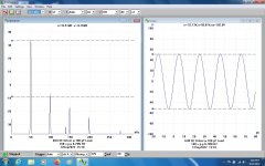
Vin: 2.22Vpp = 1.57V RMS, so enough headroom
P: 4.63W RMS
THD: 3.125%


I might have found a simple driver meeting my requirements. The circuit has a sensitivity of about 2.2Vpp, so has some headroom too. Can you experts confirm this should work fine? And maybe check my 6DJ8/6922/E88CC setup if it needs to be improved / corrected? According to LTSpice it looks OK, but who knows? Any comments?
Vin: 2.22Vpp = 1.57V RMS, so enough headroom
P: 4.63W RMS
THD: 3.125%
- Home
- Amplifiers
- Tubes / Valves
- 300B with 2V sensitivity