Forgive me Father for I have sinned... I have rigged my 300B to ... <sob> ... a SWITCHMODE SUPPLY! On the filament no less...
So I've been designing this 300B amp. I like the anode follower. I'm using only two 6J5's total - not two in parallel as shown in the schematic in above thread. I really like it. But so far I've been running the filaments on lab supplies.
Then I started designing the power supply. I've settled on using regulated supplies for the HV and the filaments. The HV supply is easy. The Maida regulator (LM317 with a BJT cascode to handle the high input voltage) is a proven concept. The power dissipation (worst case) for the Maida regulator in my setup is about 10 W (5.6 W typ). But the filament supplies are another story. At 5.0 V, 1.4 A for the 300B, 6.3 V, 600 mA for the two 6J5's, the filament supplies would dissipate 16 W (worst case -- 11 W typ). So the heat sink for the power supply needs to dissipate 52 W for two FIVE WATT amplifier channels. I'm sorry. That's ridiculous. My worst case isn't even that conservative - basically, I'm assuming that the mains voltage will be 10 % high and I disregard that the power dissipated in the regulators will be slightly less due to ripple on the supply.
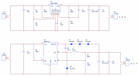
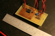
So I started looking at switchmode options. I generally default to National Semiconductors for stuff as I like their data sheets and their sample program. The parts are good too... I chose the LMZ12002 for the 5.0 V supply as it only requires a few passives to get to run. Unfortunately, its max output voltage is 6 V, so I can't use it for the 6.3 V supply. For this, I used an LM2734. I threw together a small prototype. After running for an hour, the LM2734 is up to about 60 deg C, and the LMZ is barely lukewarm (40 C). My need for a heat sink in the filament supply just evaporated.
Sound... It sounds like the midrange has cleaned up and become even more transparant. The bass seems tighter. It may be a product of my imagination, but at least I don't experience any significant drawbacks.
According to my measurements, the noise floor is 15 dB (!) lower with the switchmode supply. And there is a bit of clean-up happening around 7~8 kHz. I think the 'garbage' at 7~8 kHz with the linear supply is due to a stability problem in my ancient Sorensen 40-2 supply that I use for the 300B filament.
Measurement results, schematics and such attached. 0W_8R_Overlay.gif shows the noise floor (no input signal); 1W_8R_Overlay.gif shows the output spectrum for 1 kHz at 1 W into 8 ohm. Enjoy.
So I've been designing this 300B amp. I like the anode follower. I'm using only two 6J5's total - not two in parallel as shown in the schematic in above thread. I really like it. But so far I've been running the filaments on lab supplies.
Then I started designing the power supply. I've settled on using regulated supplies for the HV and the filaments. The HV supply is easy. The Maida regulator (LM317 with a BJT cascode to handle the high input voltage) is a proven concept. The power dissipation (worst case) for the Maida regulator in my setup is about 10 W (5.6 W typ). But the filament supplies are another story. At 5.0 V, 1.4 A for the 300B, 6.3 V, 600 mA for the two 6J5's, the filament supplies would dissipate 16 W (worst case -- 11 W typ). So the heat sink for the power supply needs to dissipate 52 W for two FIVE WATT amplifier channels. I'm sorry. That's ridiculous. My worst case isn't even that conservative - basically, I'm assuming that the mains voltage will be 10 % high and I disregard that the power dissipated in the regulators will be slightly less due to ripple on the supply.
So I started looking at switchmode options. I generally default to National Semiconductors for stuff as I like their data sheets and their sample program. The parts are good too... I chose the LMZ12002 for the 5.0 V supply as it only requires a few passives to get to run. Unfortunately, its max output voltage is 6 V, so I can't use it for the 6.3 V supply. For this, I used an LM2734. I threw together a small prototype. After running for an hour, the LM2734 is up to about 60 deg C, and the LMZ is barely lukewarm (40 C). My need for a heat sink in the filament supply just evaporated.
Sound... It sounds like the midrange has cleaned up and become even more transparant. The bass seems tighter. It may be a product of my imagination, but at least I don't experience any significant drawbacks.
According to my measurements, the noise floor is 15 dB (!) lower with the switchmode supply. And there is a bit of clean-up happening around 7~8 kHz. I think the 'garbage' at 7~8 kHz with the linear supply is due to a stability problem in my ancient Sorensen 40-2 supply that I use for the 300B filament.
Measurement results, schematics and such attached. 0W_8R_Overlay.gif shows the noise floor (no input signal); 1W_8R_Overlay.gif shows the output spectrum for 1 kHz at 1 W into 8 ohm. Enjoy.
Attachments
Last edited:
Looks like a good design choice to go switchmode supply for the filaments, heresy aside. You may be able to get away with AC for your preamp tubes though, but if not, switchmode seems a good choice.
Well done, congratulations! 😀
Would it be the switching noise of the rectifiers in your linear supply? Those 7~8kHz 'garbage' you said? And what are the upstream circuits for the SMPS chips (J1 and J3) see? They supposed to be DC sources, right? What's your solution for those?
Would it be the switching noise of the rectifiers in your linear supply? Those 7~8kHz 'garbage' you said? And what are the upstream circuits for the SMPS chips (J1 and J3) see? They supposed to be DC sources, right? What's your solution for those?
I think the 'garbage' at 7~8 kHz with the linear supply is due to a stability problem
Very cool thread. However, it will be more beneficial to compare noise and sound to a decent heater supply and not to 'garbage'. I have never seen any decent linear regulator generate such noise.
Have you tried a CCS for heaters? Or straight AC? Either will provide some reasonable sound reference.
Son, your sins are forgiven.😀
As it is exactly how I intend to power up the heaters of my next project: PP with 6N1P - 6SN7 - KT88. However, I will use industrial SMPS from Traco Power.
Cheers,
Serge
As it is exactly how I intend to power up the heaters of my next project: PP with 6N1P - 6SN7 - KT88. However, I will use industrial SMPS from Traco Power.
Cheers,
Serge
Why not the HV? Haven't gotten that far yet? 🙂
Now can you do it with a non-isolated winding, instead of wasting two floating windings on them?
Lastly, maybe you'll realize the 300B is a crummy old dinosaur and there are better ones out there... maybe a class D EL519 >😀
Tim
Now can you do it with a non-isolated winding, instead of wasting two floating windings on them?
Lastly, maybe you'll realize the 300B is a crummy old dinosaur and there are better ones out there... maybe a class D EL519 >😀
Tim
Very cool thread. However, it will be more beneficial to compare noise and sound to a decent heater supply and not to 'garbage'. I have never seen any decent linear regulator generate such noise.
I should clarify. I do realize that the buzz my Sorensen supply puts out is not ideal. But I take the output from the Sorensen into a 15000 uF cap and from there into an LM317 that sits right next to the 300B and provides the 5 V. So there is a fair amount of regulation between the Sorensen and the 300B filament. The buzz at 7~8 kHz is from the Sorensen. The noise floor, I bet is from the LM317.
Have you tried a CCS for heaters? Or straight AC? Either will provide some reasonable sound reference.
I have tried an LM317-based CCS. I was not able to distinguish between CCS and CVS. I have not tried AC, as I don't really care for 60 Hz IM products.
~Tom
Would it be the switching noise of the rectifiers in your linear supply? Those 7~8kHz 'garbage' you said?
The buzz at 7~8 kHz is a stability problem with the linear supply. I'm sure it's caused by an electrolytic cap that's dried out. I can easily see the buzz on the output voltage from the Sorensen supply when using an oscilloscope. That said, I do follow up with a hefty cap and an LM317, so the Sorensen really only serves as a pre-regulator.
And what are the upstream circuits for the SMPS chips (J1 and J3) see? They supposed to be DC sources, right? What's your solution for those?
Currently, they are HP lab supplies. HP 6236B. In the final implementation, they'll be fed from a 12 V, 50 VA transformer through the usual arrangement of diode bridges and caps.
Why not the HV? Haven't gotten that far yet? 🙂
🙂 Not a bad idea. But it's a project for another day. I can deal with the power dissipated in the Maida regulators pretty easily...
Discrete switchmode supplies tend to open up a Costco-sized can of worms. I did once design a 2.5 kV SMPS supply for a research satellite, but that was 10 years ago. Given the low amount of power needed for this project ... hmmm... NO! Must resist!
~Tom
Why resist? Give in.. give iiiinnnn....
Beef this up... ooh, it's even automotive 😀
Versions for 90-250VAC input, 100W abound...
Tim
An externally hosted image should be here but it was not working when we last tested it.
Beef this up... ooh, it's even automotive 😀
An externally hosted image should be here but it was not working when we last tested it.
Versions for 90-250VAC input, 100W abound...
Tim
Why resist? Give in.. give iiiinnnn....
Versions for 90-250VAC input, 100W abound...
Damn you! 🙂 Ahhh... The good ol' Unitrode controllers. I remember those.
Zo... I'll need roughly 160 mA at 400 V. I'd probably design for 200 mA (80 W). That's starting to look a lot like a forward converter, though, a flyback like you're using might work. If I power it from a 12 V trafo, I technically won't need the galvanic isolation. But if I power it off the mains, I would. No biggie, though, it makes the feedback (or switch drive) a bit more tricky. Last time I used two opto couplers for the feedback and some tricks to linearize them. Worked well.
If you're doing the 85~264 VAC thing, you might as well throw in the power factor correction... 🙂
I may have asked you before, but which sources do you recommend for magnetics (cores, bobbins, transformer tape)?
~Tom
Yes, Unitrode stuff, which is now TI, who makes a useful range of products themselves.
Flyback is a bit nicer for HV stuff because you don't have to fight parasitics as much. The tubescope has a 100W forward converter, and because I was unable to wind the output transformer ideally (no split primary), the HV secondary has about 100% overshoot (500V spikes, requiring >1kV rectifiers -- I ended up with doubled-up UF4007's). That one's kind of a wash, because it needs 10A of heaters, which would be annoying to provide from a flyback (40A peak!). Something lighter, with more B-supply than A-supply, would be a fine fit.
Flyback is also good at wide input ranges. TOPSwitch datasheets often show 85-265V circuits. There's not really any point in PFC at low power, but if you want to be 'nice', you'll need the additional hardware. Of course, then you can use whatever converter works best. You could even use a buck or boost converter, since the PFC doesn't have to be boost, it can be flyback, providing isolation instead.
For magnetics, besides the junk box, there are parts available from Newark and Mouser (ferrite beads, toroids, and I think I saw E cores too). Amidon has online ordering. And there are a few distributors as well.
And of course for designing them,
Magnetics
Tim
Was just looking at some of Fairchild's products... SG6901 for example. PFC, PWM in one chip. Handy... I'm sure there are others out there.
A good write-up on flyback design.
Maybe, just maybe... it's time to dust off my copy of Erickson, "Fundamentals of Power Electronics". First edition...
I'm thinking that a boost regulator to 400 V followed by a floating LM317 post-regulator to get to the 375 V I need might just be the ticket...
~Tom
If you want to play with SMPS then try the software from
PI Expert Design Software | Power Integrations
You give it the basic parameters and it gives you a parts list and even details on winding the bobbins. Pretty slick.
PI Expert Design Software | Power Integrations
You give it the basic parameters and it gives you a parts list and even details on winding the bobbins. Pretty slick.
If you want to play with SMPS then try the software from
PI Expert Design Software | Power Integrations
You give it the basic parameters and it gives you a parts list and even details on winding the bobbins. Pretty slick.
Nifty. The main issue with switchmode supplies is still sourcing the magnetics, though. Newark has some stuff but generally you have to buy in quantity and accept long lead times. I've always liked the RM cores, but they're hard to find.
I might be able to get a toroid that I like though.
~Tom
Last edited:
Nifty. The main issue with switchmode supplies is still sourcing the magnetics, though. Newark has some stuff but generally you have to buy in quantity and accept long lead times. I've always liked the RM cores, but they're hard to find.
I might be able to get a toroid that I like though.
~Tom
CWS ByteMark, largest supplier of toroids, ferrite cores, iron powder cores, MPP cores and RF cores
I had good luck purchasing some 3C8 cores for a HV switcher project a few years back. They have just about anything you need and an online shopping cart.
I would think the "E-E" core style would be suitable for ease of isolating windings and sections.
Opto feedback doesn't need to be linearized; depends on where the comparator is.
I wonder if an unregulated "PFC-only" topology would be a decent approach to powering a tube amp?
A really good primer is "Power Supply Cookbook" by Marty Brown, Newnes press, 0-7506-7329-X
Last edited:
Awesome. Good to know.
Opto feedback doesn't need to be linearized; depends on where the comparator is.
Comparator? To me comparator implies on/off control. Do you mean error amplifier?
I suppose you could power the error amp on the secondary side and drive the switch via an opto coupler. But powering anything from the secondary makes start-up a bit tricky.
I wonder if an unregulated "PFC-only" topology would be a decent approach to powering a tube amp?
I'd prefer it to be regulated so the linear post-regulator doesn't fry, and it'd need to have galvanic isolation.
~Tom
Very cool thread. However, it will be more beneficial to compare noise and sound to a decent heater supply and not to 'garbage'. I have never seen any decent linear regulator generate such noise.
Good point. Very good in fact. Tonight I rigged a 12 V transformer to a 25 A diode bridge, 22000 uF reservoir cap, and used it as the raw supply in place of the Sorensen supply. As I wipe the egg off my face, let me describe the two heater supplies under test:
Linear: LM317 fed by above raw supply supplying 5 V to the 300B filament.
Switched: LMZ12002 fed by above raw supply supplying 5 V to the 300B filament.
For both the Linear and Switched supplies, the LM2734 switchmode supply was used to supply 6.3 V for the indirectly heated 6J5 tubes. Hence, this comparison only compares the heater supply on the 300B.
In terms of sound quality, I cannot distinguish between the two. They both sound good. There's good detail on human voices, guitar string buzzing on frets, difference between "up" strumming and "down" strumming on guitars, etc. The mid seems very open and revealing. The bass is tight. The highs on cymbals are metallic and clear. I like it...
The measurements show virtually no difference between the two supply types. The 60 Hz ripple is nearly identical for the two - except the 2nd and 4th harmonics are lower with the switchmode filament supply. I expect the 60 Hz to go down further once I get my rat's nest amplifier prototype transferred to a PCB and into a metal chassis.
Attached images show the noise floor (20 kHz BW, 1 kHz BW) and the spectrum with a 1 kHz, 1 W into 8 ohm signal.
Oh... And by the way, I changed the soft-start cap, C5, to 57 uF (47 uF || 10 uF). This provides about 5.7 seconds of start-up time so the LMZ doesn't current limit during start-up. Nice, gentle on the 300B filament too.
Attachments
Last edited:
The measurements show virtually no difference between the two supply types.
Thanks for taking the trouble to measure this. Not sure i understand why the measurments are so similar but it's enough to persuade me to test the switchers myself. Great.
Thanks for taking the trouble to measure this. Not sure i understand why the measurments are so similar but it's enough to persuade me to test the switchers myself. Great.
Hey... Thanks for sticking with me here. I'm pretty thrilled about the performance of the switchmode supplies. I was a bit skeptical to start with but they turned out to be really good parts and easy to work with. If you decide to go the switcher route using National's parts, I suggest that you look at the evaluation boards also. The board layout is shown in the eval board instructions (download as .pdf from national.com). I practically copied those for my design. Also read the PCB layout instructions in the eval board instructions and application section of the data sheet.
I should clarify something:
What I meant to say is that I expect the 60 Hz and its harmonics to go down significantly once I clean up the layout of the amp. Specifically, getting a good star ground scheme going will make a world of difference.I expect the 60 Hz to go down further once I get my rat's nest amplifier prototype transferred to a PCB and into a metal chassis.
~Tom
SMPS works
I use switch mode supplys on my 300B heaters and the amp sounds (and tests) great!
I was unsure how well they would work on a directly heated cathode tube, but after building and testing the amp I have to say I'm thrilled with the results.
I was admonished for designing the amp this way, and I almost changed the design based on some very negative comments about SMPS, but I decided to try it anyway. I'm glad I did. It works and it works extremely well, at least for me. I used "cheapies" at only $20 each and simply put filtering caps across the output to help remove noise and ripple. One way to tell how much noise is being generated by the SMPS and leaking into the signal path is to measure the output noise of the amp with the SMPS on, then dissconnect it from the heaters leaving just the caps across the filaments. For a short time, even if only for a second or two, the amp will continue to operate on the thermal inertia of the cathode and the energy stored in the caps. Any reduction in noise immediately after power is cut to the heater but while it's still orange hot and the amp is still working is due to the heater supply. Don't leave the filaments off for more than a second or two though - it's not good for the tubes.
- Status
- Not open for further replies.
- Home
- Amplifiers
- Tubes / Valves
- 300B SwitchMode filament supply