I am working on the Walton 300B amplifier. I want to change over to fixed bias. I have constructed the power supply and control but have seen the negative voltage hooked up to the 220k resistor. The resistor is disconnected from ground. I have also seen the negative voltage is applied directly to the screen. Any suggestions would be appreciated.
Attachments
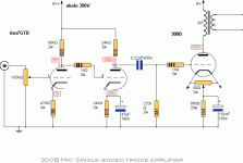
Negative voltage should be fed to the 220k resito (which should be reduced to 50-100k depending on what manufacturer's 300B you're using) unless your negative supply has resistor of similar value at its output.
Show us your PSU and we'll tell for sure.
Show us your PSU and we'll tell for sure.
Of course, when you get rid of the cathode resistor, you will need to drop the B+ voltage by the amount of the cathode voltage.
If you use fixed bias, the cathode resistor (and paralleled capacitor) is unnecessary. Instead of theses use 1R resistor, and measure there cathode "current".
Check the used 300B datasheet, the anode-cathode (which is practically grounded) voltage can't exceed suggested voltage (depends of bias and anode current), so B+ must be decrease.
Check the used 300B datasheet, the anode-cathode (which is practically grounded) voltage can't exceed suggested voltage (depends of bias and anode current), so B+ must be decrease.
Thank you. I have used a 47k resistor and 1k grid resistor. Voltage at the plate is 425. I have removed the cathode bias parts and replaced the 880 ohm resistor with a 10 ohm. I have the bias set at 700ma. What should the voltage be? Thank you.
Take care!
I hope the 700 mA is a typo.
With plate voltage of 425 you should go no further than some 70 mA for 30 watts of power dissipation.
That operating point you will have with some minus 90 volt grid bias; you should have at least minus 100 volt bias supply.
So set your fixed bias at over minus 90 volt, and carefully trim the bias until you have 0,7 volt across your 10 ohm cathode resistor.
Last edited:
You could also try moving the old cathode resistor to between the output transformer primary and the B+ and decouple with a capacitor to lower the B+ voltage, and then you would have a B+ in the neighbourhood of 360 V.
Thank you. I have used a 47k resistor and 1k grid resistor.
The coupling cap should increase to ~1uF as well.
47k is one of the worst choices.
6SN7 output impedance is not in the low side, if you want to low distortion for driving, choose greater resistor as load.
I suggest at least 200k.
Depends of the type of 300B (for example chinese, russian, JJ, Elrog, etc) each has minimal difference from "standard" WE, so for given anode-cathode voltage and anode current different negative bias need.
Last edited:
euro21,
Load for the 6SN7 is the parallel resistance of anode resistor (24k) and grid-leak resistor (220k).
That is some 21k of load resistance.
With a 47k grid-leak resistor this would drop to some 16k.
Not such a big difference, and for fixed bias you don't want more than 50k of grid-leak resistance.
Amplifiers that exceed grid leak resistance
This is one of the compromises you make when driving a 300B this way.
Real improvement is only possible when changing the driver stage to something with more current and headroom.
Discussions like these always pop up when someone comes up with these "weakish" driver stages.
Another example you will find in tubelectron's 12AX7 SRPP "ultimate" SE 300B amplifier.
Last edited:
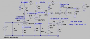
The "original" (? I have Cuno Soeren version) schematic driver stage probably designed for "standard" - ca.-75...80V - 300B bias, so at larger swing (near to A1) has growing distortion, due to the limited second 6SN7 tube's anode current.
OP killed the auto bias, so 300B plate-cathode voltage grooving from ca. 350V to ca. 410-415V, so also needed grooving negative bias voltage. At this grooving swing the second tube "run out" anode current, so it became necessary to grooving current too (within certain limits due to the DC coupling of first stage).
Even with the elevated current, the second stage distortion reached 4% at 180Vpp, and at the greater load (47k resistor) reaches 5%, due to the second stage tube characteristics and operating point (anode current near to "run out").
So, the "switching to fixed bias" is not so simple method, as "use xx Volt negative bias with xxx kOhm resistor and xxx nF capacitor), without knowing exactly how previous stages respond to this.
No free lunch, the redesign can't be float.
I think the schematic is wrong. According to the 300B data sheet maximum grid circuit resistance should be:
Fixed 0.05 Megohm
Self 0.25 Megohm
Fixed 0.05 Megohm
Self 0.25 Megohm
Why so?
0.05 megohm = 50 kohm;
0.25 megohm = 250 kohm (your circuit shows 220 kohm).
As long as the 300B is driven A1, you get away when the driver can supply enough current.
It becomes difficult when entering A2; then your circuit is not up to do that well.
Not to be unpolite but it seems your knowledge is not sufficient to see what is going on in these circuits.
My advice is to check different circuits of the various SE 300B amplifiers and learn from it.
Don't forget: 300B can only perform to it's best with ample drive; headroom can make all the difference.
I'd rather have too much driver THD than damage a 300B because of too much grid leak resistance. Ultimately cap coupling all three stages would permit the loading resistor of the second stage to be bumped up considerably, or a current source could be used instead for optimal effect.
Ultimately the original schematic fails from "I have to use octal driver tubes" syndrome. You end up with either a 6SL7 SRPP which fails horribly when it comes to AC current demands, or you end up with a cascaded 6SN7 which has too much gain.
Ultimately the original schematic fails from "I have to use octal driver tubes" syndrome. You end up with either a 6SL7 SRPP which fails horribly when it comes to AC current demands, or you end up with a cascaded 6SN7 which has too much gain.
- Home
- Amplifiers
- Tubes / Valves
- 300B BIAS