A serial capacitor will protect the tweeter yes, and a LCR notch to tame worst cone resonance has benefits too. I broke one tweeter by sweeping 15-22000Hz without highpass.
Amplifier noise is inaudible to listening area if equipment is healthy
Amplifier noise is inaudible to listening area if equipment is healthy
If you compare the two volumes, but set the frequency response to be the same (via linkwitz transform) you'll almost certainly find that the larger enclosure uses less power to get to xmax. You need to make sure you can actually get to xmax with your amplifier (referencing apparent amplifier load tab), as the volume shrinks, the power requirement in the bass region goes up very fast.LF is 9.4L. I may or may not want to add anything e.g. a weight at the bottom for stability. I may or may not have to reduce the volume for acoustic response reasons (modelled vol is about 6L - the drives are very stiff!).

Yes, I am aware of this aspect and I seem to be within both Xmax and max amp power of 250W. Bit will check again e.g. for the 4Ohm load case.
First trial fit of drivers on the front panel.
The spacing between LF and MF is dictated by the internals - flaring out cutouts behind both drivers and then a 19mm partition. I am also thinking where to put the LED and IR receiver pipe. Between there would be nice, but the partition is in the way. I think I can squeeze it in.

The spacing between LF and MF is dictated by the internals - flaring out cutouts behind both drivers and then a 19mm partition. I am also thinking where to put the LED and IR receiver pipe. Between there would be nice, but the partition is in the way. I think I can squeeze it in.
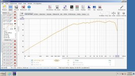
I was not sure if I should smooth the edges of the baffle around the tweeter or mid, so just did a baffle response simulation using this simulator and it is eye-opening!
With sharp-edged baffle as in the pic above there is a very clear 6dB unevenness (+4/-2dB) in the critical 1-2kHz range.
With smoothed edges it is more than twice better, under 3dB total. Very effective, for both the tweeter and the mid.
So, I definitely need to smooth the edges!
I did not plan for this operation and the only tool I have for this is an oscillating tool. Will try to manage. Do a trial shape etc.
Last edited:
... so much ...That tweeter will not be
affected by sharp edges!
Is this because of the waveguide? I do not know how to simulate for the waveguide.That tweeter will not be affected by sharp edges!
Try changing the diameter to 2.5" in the sim to get an idea. I set mine on top of a speaker box, and it measured pretty good, even with the flange edges exposed.
I have this tweeter. It seems indifferent to the baffle. Mount yours on a scrap baffle, and see.
https://www.parts-express.com/Peerl...eeter-with-Waveguide-6-Oh-264-1386?quantity=1
Also, there may be trends in the response that can be worked around when you make a x-over.
So show us the diffraction model for the two drivers, and lets see.
Last edited:
I know you're concerned with work space. You can make a scrap baffle out of almost anything. Pink foam from a hardware store is common and easy.
But otherwise, yes the waveguide's purpose is to control directivity. The midrange driver will almost certainly be the one to model for diffraction purposes.
Also, model and plan to tune for an off axis listening position. Diffraction ripples get smoothed out some when you move off axis.
But otherwise, yes the waveguide's purpose is to control directivity. The midrange driver will almost certainly be the one to model for diffraction purposes.
Also, model and plan to tune for an off axis listening position. Diffraction ripples get smoothed out some when you move off axis.
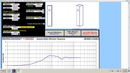
It wasn’t so much how bad the simulated response was with sharp edges, it was mostly how much better the response was with smooth edges. Very pronounced improvement, looks worth doing. I will attempt to bevel the corners in the tweeter-mid area.
The midrange improvement (from smoothed edges) was as good as the tweeter improvement.I know you're concerned with work space. You can make a scrap baffle out of almost anything. Pink foam from a hardware store is common and easy.
But otherwise, yes the waveguide's purpose is to control directivity. The midrange driver will almost certainly be the one to model for diffraction purposes.
Also, model and plan to tune for an off axis listening position. Diffraction ripples get smoothed out some when you move off axis.
- Home
- Loudspeakers
- Multi-Way
- 3-way to active - Hypex FA253 - learning project