2x CA26RFX
I get a minimum of 80liter with 0.7Qtc
To make room fore variables and with less risk of peak/boom a Qtc of max 0.65 gives 100liter
A good BR seems to me would be 160liter
And those are netto volumes
I would put yet another 10-15liter to those
I dont claim my calculations are better or even correct
I get a minimum of 80liter with 0.7Qtc
To make room fore variables and with less risk of peak/boom a Qtc of max 0.65 gives 100liter
A good BR seems to me would be 160liter
And those are netto volumes
I would put yet another 10-15liter to those
I dont claim my calculations are better or even correct
I do not dispute yours, they may be very accurate, and mine may be far off
I only say that if you approach the lower limit there is a risk, like say if driver specs are a bit off
Thats why I personally would choose a bigger box, to make more room fore variables
With closed it seems like it cant get too big, only pointless
But too small could get very unfortunate
Its just a note of caution
Last edited:
Well I have just simmed the whole thing in akabak, when I say the whole thing, baffle, drivers crossover and rear wall 🙂 The tweeter is sus because I don't have the T/S params for it, and also there is something very wrong with the reponse graph above about 10K.
This is 110L with the ports Andre specified, all the crossover components specified, and Rabitz inverted mid/tweeter (much better than with tweeter on top in the sim)
There is something very wrong with my model with repsect to the tweeter/mid but I think the bass part is probably somewhat accurate (although I'm not convinced it is doing ported, maybe sealed... I've attached two graphs, one with the speaker 1M from the rear wall, and the other with the speaker 20M from a rear wall. Unfortunately akabak can't simulate (at least I don't think it can) the chamfers on the front baffle, for that I'd probably use BDS. but not tonight!
I basically hacked one of the akabak exercises for this, and I've quite probably stuffed something up but it is a starting point 😉 I'll see if it will allow me to attach the akabak script in case any one is interested.
Tony.
PS. Navin, I thought it was really out of character for you to have specified a coil with 3 ohms DCR I was right because you didn't!!! SORRY! I should read more carefully!
Attachments

Hi all,
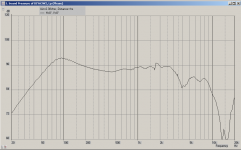
I know the MCA15RLY is an excellent dedicated midrange, but I'm wondering if the ER15RLY mid/woof could be used as an alternative? Slightly higher Qts and lower SPL but wow what a response curve... Zaph graph attached
seasons greets, Grant
I know the MCA15RLY is an excellent dedicated midrange, but I'm wondering if the ER15RLY mid/woof could be used as an alternative? Slightly higher Qts and lower SPL but wow what a response curve... Zaph graph attached
seasons greets, Grant
Attachments
I also think 3 dB would be enough, some say 4dB though? I prefer to use as little as possible (rather no) series resistance in a XO, maybe that's the biggest reason why I'm leaning towards using two woofers.
Yes 3-4db is adequate the difference (between 3 and 4db) will be a matter of personal taste.
Yes series resistance should be limited especially with woofers are it affects the damping factor directly.
With closed it seems like it cant get too big, only pointless
But too small could get very unfortunate
Its just a note of caution
If the box is a bit too small one can go aperiodic. granted there are limits to how small the box can be (how high a Qts).
PS. Navin, I thought it was really out of character for you to have specified a coil with 3 ohms DCR I was right because you didn't!!! SORRY! I should read more carefully!
no harm done. series DCRs should be kept below 0.25ohms.
I know the MCA15RLY is an excellent dedicated midrange, but I'm wondering if the ER15RLY mid/woof could be used as an alternative? Slightly higher Qts and lower SPL but wow what a response curve... Zaph graph attached
seasons greets, Grant
midwoofers tend to have higher mms than true midranges. if one is corssing over at 100hz or so then a midwoofer is justified but if one is corssing over at 250Hz+ then a good midrange is better suited.
hehehe Navin, if nothing else I guess it was a good ilustrative excercise as to the effects of too higher DCR in a series coil 🙂
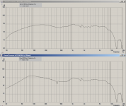
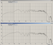
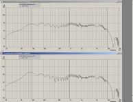
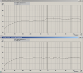
I've done some more playing with akabak today and have some new results. The first model I posted was definitely faulty, and the bass reflex was not working as intended.
The attached images are models with single CA26RFX in 73L box tuned to 29Hz (top graph) compared to two CA26RFX in 110L Box tuned to 25Hz (bottom graph).
The first is at a distance of 20M from rear wall to give an idea of the 4pi radiation. The next is at 75cm from rear wall, then 1M and then 1.5M and finally 2M.
One of the things I found was even at the 20M distance the baffle step didn't seem right, but a bit of fiddling revealed that the 1M height of the baffle seems to be having the same effect as a wide baffle and is actually re-inforcing the SPL.
Another thing I found was that the position of the woofer (in the single model) had a marked effect on the response. If it is near the bottom of the box there is a large dip in the response between 200 and 500Hz. The single and dual models are both with the woofer close to the tweeter, and then the second woofer directly below.
There apears to be some phase? issues (at least in this sim) with the crossover points... putting in an offset (into the baffle) for the tweeter seemed to improve things a bit in this regard, but crossover optimisation might help as well.
But all in all I think Andres' initial crossover looks like a good starting point! Of course this is just a sim and we would need real measured data to really optimise but certainly a very good starting point 🙂
I also substituted in a morel MDT30 tweeter simply because it has a flat response and I had the T/S params for it (as I can't find for the params for the seas, and akabak won't model it without). The reponse after 10K is still a bit of a mystery....
Oh the other thing is that I have guestimated the driver geometry for both the woofer and mid, from the datasheets diagrams (that is the cone depth) which does effect the simulated response.
Tony.
Attachments
Last edited:
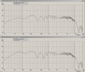
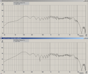
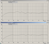
ok here is a comparison between having the woofer at a centre height of 60cm (top graph) compared to at a centre height of 15cm) bottom graph. I can only guess that the path length difference between the two heights and the mid causes some cancelation effects causing the more pronounced dip at around 500Hz.
Also I've attached the two different akabak scripts in a zip file in case anyone is interested. Note there is a lot of crud in them which is commented out 😉 I'm still getting up to speed with akabak!!
Tony.
Also I've attached the two different akabak scripts in a zip file in case anyone is interested. Note there is a lot of crud in them which is commented out 😉 I'm still getting up to speed with akabak!!
Tony.
Attachments
Another thing I found was that the position of the woofer (in the single model) had a marked effect on the response. If it is near the bottom of the box there is a large dip in the response between 200 and 500Hz. The single and dual models are both with the woofer close to the tweeter, and then the second woofer directly below.
Roy Allison wrote a few papers on this some years back.
AES E-Library: The Influence of Room Boundaries on Loudspeaker Power Output
http://www.audioxpress.com/magsdirx/voxcoil/addenda/media/mowry509.pdf
This is in reference to the lower graph in the above post as it's a way to overcome the dip plus brings in the issue of room boundaries which play a major part in loudspeaker design.
I've posted this somewhere before but Roy F. Allison (Allison Acoustics) did an article in the 70's or 80's.
He came up with the woofer placement close to room surfaces, set the crossover so the operating range of the woofer is limited to well below the notch (suckout) frequency so the reflected pressure is in phase and will reinforce the woofer output, locate the midrange far enough away from the boundary intersection so it's at least 1/2 wavelength distant at the crossover frequency and above. All this has to be determined with knowing the proximity and number of room surfaces.
From his information we get suckouts at these frequencies at these mutually perpendicular boundary dimensions (a small list of examples).
160mm=621Hz
200mm=497Hz
300mm=331Hz
400mm=248Hz
500mm=199Hz
600mm=166Hz
700mm=142Hz
800mm=124Hz
900mm=110Hz
These suckouts can range from 1.5dB (single boundary) up to over 10dB (3 boundaries).
What it all means that his preferred location of the woofer was close to the floor and mid was high up the box to overcome where the reflected pressure from boundaries are out of phase with the motion of the driver. This meant the crossover to the woofer was set to suit these parameters. You can see this pattern used in a lot of commercial speakers with low woofers with low crossover points and mids up high.
Of course there are other issues to address in woofer placement and crossover frequency but is one point of view but as with all speaker design, fix one area and can create an issue elsewhere..... but that's the fun of it to choose the paths.
Thanks Navin and Rabbitz, I'll have to do some reading. Yes you did mention it earlier Rabbitz, I was going to do some experimenting with my existing 10" boxes but discovered I could simulate in akabak (It also lets me put in side walls if I so desire).
Note that the models I have posted are still flawed... I forgot half of the bandpass filter!! woops, I only put in the lowpass section, not the highpass... helps with the dip at around 500Hz with the highpass in place 😉 Will post an update tomorrow, I'm off to bed!
Tony.
Note that the models I have posted are still flawed... I forgot half of the bandpass filter!! woops, I only put in the lowpass section, not the highpass... helps with the dip at around 500Hz with the highpass in place 😉 Will post an update tomorrow, I'm off to bed!
Tony.
What it all means that his preferred location of the woofer was close to the floor and mid was high up the box...Of course there are other issues to address in woofer placement and crossover frequency...
JM Labs-Focal's Maestro Utopia addresses both these issues by having 2 woofers. The upper woofer ensures integration with the midrange, the lowe woofer resolves the boundary issues. Another reasson to use 2 woofers! 😉
http://www.focal-fr.com/catalogue-docs/EN/32/files/2407.pdf
http://www.focal-fr.com/catalogue-docs/EN/32/files/2362.pdf
You must have sneaked that post in while I was typing.
Sorta like Emilio Lopez (in Mr. Deeds). 😀
YouTube - The Sneakiness...
I would have said that 3 woofers was the ideal, but you just can't get 16 or 24 R drivers so easily.
Two drivers fire forwards, as stated 1 near floor, 1 close to mid/tweeter
Third woofer driver fires to the rear and takes care of baffle-step, although I suppose you could parallel 2 * 8R woofers and run them in series with a 2 or 4R driver the skill and expertise to select drivers and XO components to do that to perfection eludes me still.
I would have said that 3 woofers was the ideal...Two drivers fire forwards, as stated 1 near floor, 1 close to mid/tweeter...Third woofer driver fires to the rear and takes care of baffle-step....
that is too complicated...
1. since much of the baffle step is with the midrange all we realy need to do is use the woofer's (1 or 2 woofers does not matter) midrange response to compensate for this.
2. for those who have seen the focal utopia maestro "2 woofer" pdf that was posted earlier my vision was to have one woofer up near the midrange and the second woofer firing downwards (10" woofers esp the Seas woofer we have chosen does not have too big a mms and hence can be3 used this way) to compensate for boundary reflections (a derivative of the Allsion CD9's bass section)
Allison CD 9 Manual | The Classic Speaker Pages
Hmmm the learning curve on akabak is steep.... The models I have posted so far should be ignored, I had the co-ordinate system for the baffle and rear-wall reflector all wrong. I get a nice tweeter response now (helps if it isn't positioned 80 odd centermeters above the baffle) 😉 All graphs previously posted should be ignored 😉 I might upload some new ones tomorrow if I feel confident I have ironed out the bugs...
Tony.
Tony.
kits
would these concepts be of any help in design? go to suggestions for mtm mains in this forum
they are still at the cutting stage of the project
cheers speedie
would these concepts be of any help in design? go to suggestions for mtm mains in this forum
they are still at the cutting stage of the project
cheers speedie
would these concepts be of any help in design? go to suggestions for mtm mains in this forum
they are still at the cutting stage of the project
cheers speedie
and miss out on all this fun 😉
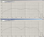
OK I'm going to post one more akabak model. I think now it is somewhat closer to being "correct"
The first graph shows the model without any BSC and the second is with 4db of BSC.
The second graph shows the BSC corrected on top and then the same with Rear wall (and floor) reflections turned on for just the woofer (rear wall at 1M behind). I've also set the absorbsion coeficient for the walls/floor to 0.33 to tame the peaks and troughs a bit, as the akabak manual states that they tend to be exagerated.
The crossover was initially done from within akabak as 2nd order linkwitz riley theoretical, then synthesised... I have hacked the midrange values to try and smooth out the reponse a little, so I really have no idea what the real alignment is now.
Crossover components as follows: (note I have no idea what I'm doing 😉 and I haven't adjusted for available values... )
BSC (from MJK's excell spreadsheet sans the zobel, as it dropped the mid too much)
1.8mH in parallel with 4.6ohm resistor This is in front of ALL other filter elements...
low pass: 6.93mH in series, 41.65uf to ground.
Mid: --- 0.35mh in series 7uF to ground --- 27uF in series 6.53mH to ground.
Tweeter: 5.71uF in series 0.95 mH to ground
As I said I have no idea what I am doing, but the graph doesn't look too bad to me 😉 4db BSC is probably going to be too much though IMO if close to a wall.. even if it is a decent distance away I think the floor reinforcment probably boosts it more than some peoples taste would allow.
I'm now going to cease posting akabak models and concentrate on modelling my own speakers for which I can take measurements and compare to the simulated results, that way I think I can get a feel for whether I am using the tool correctly, and what it's limitations are 🙂 If anyone with experience wants to grab the model and improve upon it, or point out where I have made gross errors, that would be great!! I know the first lot had major major problems, so I'm guessing I haven't quite got there yet 😉
Tony.
Attachments
Last edited:
The use of the parallel LR circuit to me is not the way to go with BSC on a 3-way.
It works great on FR. It can be used on 2-ways but it can be achieved in the filter design with better results IMO.
One advantage of 3-ways is your can get BSC easier than the others if you set the woofer crossover point in the right place and work on the levels of the mid and tweeter. If that drops the SPL too much then you have the option of the second woofer either running dual or as a 3.5 way (depends on the baffle step frequency and actual SPL lift required). Generally I've found the actual baffle step correction frequency is a lot lower than the calculated one (115/Baffle Width). For example I had baffle step F3=360Hz but the 0.5 woofer was crossed over around 150Hz to give the required BSC. Full BSC with the 0.5 woofer can be too much due to other factors such as the room and speaker positioning.
- Home
- Loudspeakers
- Multi-Way
- 3-way reference project??