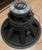
These specs are excellent for a closed box of 80L. Add series capacitor of roughly 800-1000uF gives, wild guess, -8db at 25Hz.@TNT Hadex Q378 (datasheet here https://hadex.cz/spec/q378.pdf). It is relatively cheap and has a low fs. Its performance is reported to be pretty good by the local guys. For serious PA, it is not really suitable, there are much better drivers that can be used in smaller volumes - it seems to fit my purpose though.
Bass reflex with a steep 4th order highpass seems to give more headroom on the low end. But that is step 2 anyway. First, the prototype horn including mid enclosure must be built. I assume the large box will be built first as sealed anyway, since it would be quite hard to calculate the volume, much easier to measure by woofer resonance shift🙂

Hi pelanj, thanks for the kind words earlier.🙂Bass reflex with a steep 4th order highpass seems to give more headroom on the low end. But that is step 2 anyway. First, the prototype horn including mid enclosure must be built. I assume the large box will be built first as sealed anyway, since it would be quite hard to calculate the volume, much easier to measure by woofer resonance shift🙂
Your progress is looking good. Box volume starts to grow on it's own, just fitting in the dang 18"s, huh?
But it's a shame the horn robs so much interior volume.
I've taken my big guy apart, to add reflex ports. The sealed 18"s were decently strong, but not with the authority and ease i'm used to.
Have 4" pvc drain pipe....plan to put a port in each corner of the horns front flat faces. Should be pretty easy, and i imagine will work well.
Won't happen till spring though, as I'm going to build it outside on the deck a rolling stand...
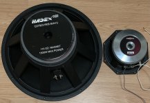
Time to measure and weigh the drivers. The 18" is 10.8 kg, the 8" 4.3 kg, CP755 3.2 kg and DCX464 3.6 kg. That is 18.3 or 18.7 kg for the drivers only. I wonder how much the box will be. I am pretty sure I will not get below the legal single man carry weight of 30 kg total. 40 kg would be nice though, that one can still pretty easily manipulate with - like my Marshall 1960BV guitar cabinet.
Attachments
Poplar plywood could save at least 1/3 of the box weight if used on the whole box. Pine plywood is also lighter than birch. The question is, are they strong enough? I think with some smart bracing, 15 mm (or 18) poplar plywood would work and still be relatively light as e.g. 12 mm birch. Or maybe I could use the lighter material just for the horn. Anyway, the horn prototype will be 16 mm chipboard due to price🙂
Pine ply is strong but it does dent more easily if something hits it. It also warps very quickly once cut and needs a lot of clamping or screws to keep it in place while the glue sets. WISA branded Spruce ply is probably one of the best but won't be cheap. Premium face Hoop Pine ply used to be more expensive than Birch in Australia.The question is, are they strong enough? I think with some smart bracing,
Some very rough calculations gave the following results:
Approximate horn volume including walls: 105 l
Approximate external box volume: 316 l (including the horn)
Approximate surface: 3.25 m2
Approximate box weight with 15 mm poplar plywood without braces: 22 kg, saving around 12 kg compared to 15 mm birch plywood.
External dimensions are around 93 cm width, 78 cm height and 44 cm depth + 11 cm externally mounted CD.
So I will most probably not be able to keep the box weight below 40 kg, since this does not include the mid enclosure and bass reflex shelves. Somewhere between 45 - 50 kg total is quite a realistic estimate including all the hardware, subpanels, etc. Not light or easy to handle, but manageable. Just a little bit larger than my Marshall 1960 BV cabinet and smaller than one my bass horns.
Last edited:
Well, it seems that 3 cm make a huge difference. Instead of 800 Hz at 10 cm, the cancellation notch moves down to devilish 666 Hz at roughly 13 cm. That is for center placed circular port. I hope I will be able to bring this back up by shifting the entry port closer to the throat. Definitely worth having a few extra mounting plates for experimenting with the port placement.
Edit: No, this is something else - most probably front or back chamber resonance, that should be possible to handle.
Where does this resonance come from? I did not have it before.

Edit: No, this is something else - most probably front or back chamber resonance, that should be possible to handle.
Where does this resonance come from? I did not have it before.
Last edited:
The resonance does not show when simulating the mid as offset horn.

Edit: It does show up somehow. This is with unmasked resonances (in grey):

I still do not understand the down/up jump from the previous post. HornResp records attached.
Edit: It does show up somehow. This is with unmasked resonances (in grey):
I still do not understand the down/up jump from the previous post. HornResp records attached.
Attachments
I had a 16 cm port instead of 1.6 cm port on the mids. The resonance gets smaller, but I still do not get it why it was not there before.
Edit: I have just discovered something. When using only mids, the notch disappears (simulating as 2 way MEH only). Could the notch be from interaction between bass and mid chambers?
Edit: I have just discovered something. When using only mids, the notch disappears (simulating as 2 way MEH only). Could the notch be from interaction between bass and mid chambers?
Last edited:
Heureka! The resonance in mid response comes from the bass chamber. When I reduce the volume to something small, it disappears again. I hope I will not see this in the build. If yes, filling the volume below the bass cone as much as possible should help as well.
This is just a preview of the arrangement. 18" will be on the bottom, 8" on the top in a small internal enclosure. The bass reflex ports will be placed on the sides of the front extension panel. The bottom panel will be in 3 parts, the middle part being the access opening for the 18". This approach will need some extra bracing at least on the bottom. Maybe 12 mm birch ply could be used then.

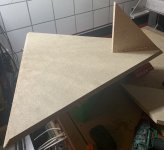
First panel was cut. This was for the first time trying to cut something longer than my CNC is in 2 steps using alignment pins. It worked quite well, the error over almost 1 meter is around 0.5 mm. Mostly due to the board bending, I need to fix it better to the wasteboard.
Attachments
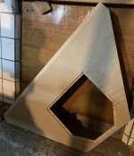
While tuning the new CNC spindle for another project, I tried to cut some more panels. I made a mistake with the panel shown above - I used a wrong STL. It had to be fixed by hand.
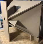
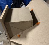
I made a fixture for the glue up (the cross like thing) and 3D printed spacer for the top. It worked really nicely, the glue up was a breeze with these. A battery powered brad nailer helped a lot to hold everything in place.
I will slowly continue to glue the other parts while the CNC is cutting another things. Some sanding will be needed, but not too much, since it is just a test model from cheap material. I also want to try out bracing strategy so that I can build driver access doors on the top and bottom.
Attachments
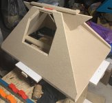

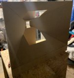
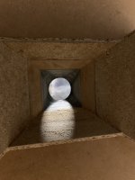
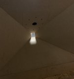
The frame is glued together, now it can stand by itself. Now the bottom opening will be blinded and 8PE21 adaptor plate will be mounted on top, first without an enclosure on the back. Edit: Forgot to attach the pictures🙂
Attachments
-
 61696A0C-9BC9-49B8-B6F9-D410ADDD6437.jpeg434.3 KB · Views: 154
 -
 E24B0708-8B36-480D-8C91-6D9A8302AEF8.jpeg420.5 KB · Views: 145
 -
 F0347280-8CB2-4201-975B-AD1760B0AD90.jpeg321.9 KB · Views: 153
 -
 97A1BCC9-6F77-4486-A406-5843AAA3BCDC.jpeg447.1 KB · Views: 154
 -
 A3B15A5C-2627-4C7B-B9D7-33DC9AA3DD36.jpeg384.6 KB · Views: 158
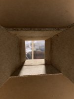
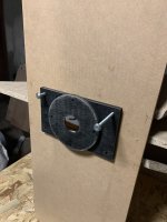
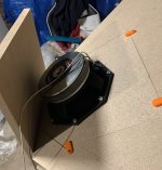
I thought I would do this tomorrow, but I managed to test the mid woofer mounting and to blind the bottom opening - the plates are held by small 3D printed brackets. One of the screws is not accessible, so in future I will use only 7 of them.
Attachments
- Home
- Loudspeakers
- Multi-Way
- 3 way MEH with 1.4" CD - 3D print and CNC