Hi All,
I would like to have a crack at building the 3 way version of the LR crossover from the Elliot Sound Products site: Linkwitz-Riley Electronic Crossover
This has been occasioned by me clearing up my bits box and finding more OPAMPS than I remember having...
Since the site operator does not offer the 3 way as a PCB I am going to also take the opportunity to try and learn to use some PCB layout software to design a board.
I have 10x LF357n, 10x TL071, 4x AD548KN and a random uA 739.
My first question is in regard to the LF357n OPAMps, they seem much faster and better spec'ed than the TL07x series, are they suitable for audio use? If they are I was thinking of using them for the input buffers and HF sections.
The second is that I would like to try and design a PCB with a ground plane, for fun and experience, if that would be of any benefit to a purely analogue PCB?
The LF357 are uncompensated and are unstable below a gain of 5, so not suitable for most filter circuits.
Groundplanes are very useful in high gain amplifiers to reduce unwanted coupling between output and input (creates oscillation), for active filtering its not so critical but will help cut down crosstalk, EMI, general signal cleanliness.
You know a 3-way active crossover is basically two 2-way crossovers cascaded - so 2-way PCBs can be doubled up if you want and the capacitor footprints are flexible enough.
Yes, P09 is a basic but superb design, very versatile and easy to understand and build, and well supported by Rod.
With a little imagination and some jumpers, you can use it for various xover configurations. It does NOT need to be LR4.
The pads do lift easily, so be very careful when desoldering, or be prepared to hardwire between components if necessary. The PCB is big enough that it's not so hard to do.
But I disagree with your basic premise to build an active xover simply to consume oddball opamps. I have found this circuit to respond well to better grade opamps, despite Rod's statements to the contrary. In fact, the very best high frequencies and overall sound were achieved using discrete opamps. 😱 😱 Yes, better than any monolithic chip that I tried.
Tom E
Rod Elliott does sell a PCB for that project, P09. They are what I use.
Ah, I must have misread the website. 🙂
That does simplify matters but his board is designed around dual 8 pin packages and I have single Opamp ICs.
Having read the post beneath yours about the design and also the comments above about half of the opamps I have being unsuitable anyway, I am thinking of perhaps I have gotten the project **** about face by trying to make the wrong stuff fit a specific design.
Yes, P09 is a basic but superb design, very versatile and easy to understand and build, and well supported by Rod.
With a little imagination and some jumpers, you can use it for various xover configurations. It does NOT need to be LR4.
The pads do lift easily, so be very careful when desoldering, or be prepared to hardwire between components if necessary. The PCB is big enough that it's not so hard to do.
But I disagree with your basic premise to build an active xover simply to consume oddball opamps. I have found this circuit to respond well to better grade opamps, despite Rod's statements to the contrary. In fact, the very best high frequencies and overall sound were achieved using discrete opamps. 😱 😱 Yes, better than any monolithic chip that I tried.
Tom E
Thanks Tom, what you say makes a lot of sense. I have a DSP for active filtering, it would perhaps be interesting to build this filter as the designer intended (bearing in mind your comments about upgraded opamps) and compare it to the digital equivalent.
Is changing the opamps in the ESP product above be as simple as using sockets and swapping the op amps?
Dual to single adapters are available to fit two single pianos into the dual pattern, and they work well. Personally I use them in a DAC I put together.
If you want a three way just use two p09 boards 🙂 cascade them as the schematic shows and you're all set.
If you want a three way just use two p09 boards 🙂 cascade them as the schematic shows and you're all set.
Sorry to spoil all the fun, but textbook electrical filters do not work with real drivers. Any discussion about "better" opmaps or pcb layout is fairly irrelevant, given the SPL errors.
Boden, they work for me. I don't know what you do with circuits to make them not work, but your persistent negativity towards people who want to experiment may be the reason you are on my ignore list.
Dual to single adapters are available to fit two single pianos into the dual pattern, and they work well. Personally I use them in a DAC I put together.
If you want a three way just use two p09 boards 🙂 cascade them as the schematic shows and you're all set.
That’s a great idea, thank you. 🙂
Sorry to spoil all the fun, but textbook electrical filters do not work with real drivers. Any discussion about "better" opmaps or pcb layout is fairly irrelevant, given the SPL errors.
I’m new to all of this, would you elaborate please?
It's mainly that real world drivers in most box designs won't have a flat enough response to be used with a simple filter arrangement like the LR4 types, although this limitation also applies to passive crossovers in the same cases. If you have a design that will let the driver have a very flat response it will work well enough however. Boden is exaggerating a bit. Some adjusting for the difference in response and all that will still be needed in many cases to get the correct acoustic response.
The bass to mid transition is not the problem, but mid to tweeter is. Apart from non-perfectly behaving drivers (due to e.g. diffraction effects)for a perfect acoustic fit in LR4 the so called acoustic centres of the drivers must be in the same plane. Only if you are lucky that will be the case.
Strictly speaking first of all, all drivers raw responses must be measured in-box-on baffle. Then the so called relative offset between the drivers must be established. Only then can the measured data be put into a simulator in order to design a suitable filter.
This will get you started: https://www.physical-lab.com/images/pdf/FilterShopApp_05.pdf
Sorry to spoil all the fun, but textbook electrical filters do not work with real drivers. Any discussion about "better" opmaps or pcb layout is fairly irrelevant, given the SPL errors.
I agree, They do not work, But doesn't mean Active xovers are completely useless
Boden, they work for me. I don't know what you do with circuits to make them not work, but your persistent negativity towards people who want to experiment may be the reason you are on my ignore list.
Doesnt always work

The trick is to Adapt the textbook crossovers to real world drivers.
1. Measure drivers, and input to crossover software
2. recreate active Crossover schematic like xsim/vituixcad with standard textbook values for your desired crossover frequency
3.Adjust Values, while keeping an eye on filter slopes so that you dont degrade Q by too much.
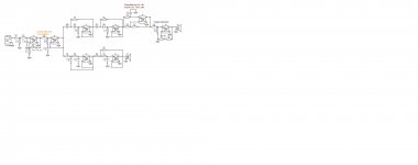
Attached a schematic for xsim for 2-way as an example. Input the frd and zma, start adjusting values.
Vituix Cad can do this as well.
Hope this helps
Cheers
Mallik
Attachments
Thank you chaps, if I have understood correctly the benefits of such a driver are not fully realised unless it is engineered to match the application.
That makes sense and would be discouraging if I was intending to render a finished commercial product to a customer or something like that.
For my purposes however the news is delightful as it means there is more to bugger about and fiddle with, I am a hobbyist after all. 🙂
It seems that given the possibility of time alignment and arbitrary x’over and slope factors DSP is indeed the easiest solution to active filtering.
The wonder how close I can hardware to my existing DSP results in that case.
It also seems that this has gone from an excuse to use up oddball Opamps to me having ordered some fancy Opamps for another full blown Project... thanks chaps... 😀
Good news!
The adventure of DIY is alive and well. To get a perfect speaker requires enormous resources at equally enormous cost, which even highly capitalised cannot achieve due to variations in the manufacture of drivers.
Liberate yourself from the strictures imposed by pedants.
The adventure of DIY is alive and well. To get a perfect speaker requires enormous resources at equally enormous cost, which even highly capitalised cannot achieve due to variations in the manufacture of drivers.
Liberate yourself from the strictures imposed by pedants.
Btw, if you like to tinker and look for a more flexible solution, it's worth having a look at the Rane AC 23 schematic, which is available here: https://www.rane.com/pdf/old/ac23ssch07.pdf
TI also has an interesting design: http://www.ti.com/tool/TIPD134
Two good sources of inspiration beyond the more simple ESP board.
TI also has an interesting design: http://www.ti.com/tool/TIPD134
Two good sources of inspiration beyond the more simple ESP board.
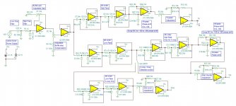
Better Schematic
The Rane is way too complex, and the TIDP134 has a 2-way limit.
ESP is the best, Although not on the PCB board, the required circuits are mentioned in different articles.
Use the attached schematic for a more complete design.
Credits: ESP
Cheers
Mallik
Btw, if you like to tinker and look for a more flexible solution, it's worth having a look at the Rane AC 23 schematic, which is available here: https://www.rane.com/pdf/old/ac23ssch07.pdf
TI also has an interesting design: http://www.ti.com/tool/TIPD134
Two good sources of inspiration beyond the more simple ESP board.
The Rane is way too complex, and the TIDP134 has a 2-way limit.
ESP is the best, Although not on the PCB board, the required circuits are mentioned in different articles.
Use the attached schematic for a more complete design.
Credits: ESP
Cheers
Mallik
Attachments
Last edited:
- Home
- Source & Line
- Analog Line Level
- 3 way LR crossover project using existing OPAMPS