side-side near floor woofers
Have you considered mounting T_horn(ear level) - M_horn -W_midwoofer on the front baffle, and mounting the two woofers side-side in a counter-force construction near the floor? The cabinet will need to be tall enough for the woofer volume, but the T_horn stays at ear level. If you port the bottom woofers, you would want a front-rear pair of counter-force ports.
Have you considered mounting T_horn(ear level) - M_horn -W_midwoofer on the front baffle, and mounting the two woofers side-side in a counter-force construction near the floor? The cabinet will need to be tall enough for the woofer volume, but the T_horn stays at ear level. If you port the bottom woofers, you would want a front-rear pair of counter-force ports.
Time to update the thread.
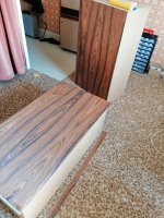
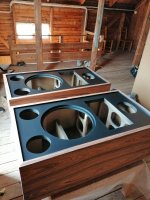
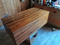
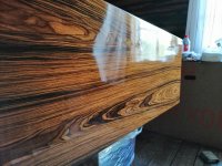
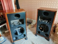
I made some progress since the last posts. The cabinets have been built and finished. Material MDF 20 and 30 mm. I decided to go all the way and choose rosewood veneer as a finish. The top coat is oil based varnish. There are some imperfections now, but I put 6 thick layers of the coat and the plan is to rag and polish the finish as it completely dries off. Unfortunately oil based varnish takes really long time to dry, so I decided meanwhile to move on with the “sound part”.
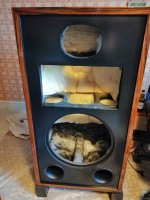
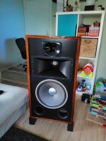
Once al the drivers are in place I made measurements: impedance of each driver as well as frequency responses both with a SET amp and a Hypex class D. Also I was listening to the speakers with an active DSP crossover for a couple of days with different configurations. My original plan was to cross all three speaker elements passively and power it by a SET 6s41s amp. While sounding absolutely amazing with the two horn drivers, the SET amp is not at all deliver any energy in midbass section. Having the Hypex amp for the midbass driver and the SET for the horns is by far the best sounding combination I managed to achieve. So let it be this way. In this case I only need to passively cross the two horns.
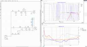
Having .zma and .frd files generated I started playing with crossover in Xsim. I started with some designs I was inspired by: JBL and Klipsch networks. I did my best to simulate the frequency response while keeping the impedance curve as much as possible “tube friendly”. The impedance however, does not look very good still. I assume it is because the two horns have different depth and the drivers are some 5" out of phase between each other.
In attachments there are a few pictures of the finishing process and the speakers as well as the crossover simulated. I promise to make better pictures when I am done with everything and finish the finish.
I would like to ask some opinions and advice maybe which way to go and whether the crossover graphs look reasonable to do some prototyping.
Thanks/
Anton
I made some progress since the last posts. The cabinets have been built and finished. Material MDF 20 and 30 mm. I decided to go all the way and choose rosewood veneer as a finish. The top coat is oil based varnish. There are some imperfections now, but I put 6 thick layers of the coat and the plan is to rag and polish the finish as it completely dries off. Unfortunately oil based varnish takes really long time to dry, so I decided meanwhile to move on with the “sound part”.
Once al the drivers are in place I made measurements: impedance of each driver as well as frequency responses both with a SET amp and a Hypex class D. Also I was listening to the speakers with an active DSP crossover for a couple of days with different configurations. My original plan was to cross all three speaker elements passively and power it by a SET 6s41s amp. While sounding absolutely amazing with the two horn drivers, the SET amp is not at all deliver any energy in midbass section. Having the Hypex amp for the midbass driver and the SET for the horns is by far the best sounding combination I managed to achieve. So let it be this way. In this case I only need to passively cross the two horns.
Having .zma and .frd files generated I started playing with crossover in Xsim. I started with some designs I was inspired by: JBL and Klipsch networks. I did my best to simulate the frequency response while keeping the impedance curve as much as possible “tube friendly”. The impedance however, does not look very good still. I assume it is because the two horns have different depth and the drivers are some 5" out of phase between each other.
In attachments there are a few pictures of the finishing process and the speakers as well as the crossover simulated. I promise to make better pictures when I am done with everything and finish the finish.
I would like to ask some opinions and advice maybe which way to go and whether the crossover graphs look reasonable to do some prototyping.
Thanks/
Anton
Attachments
-
 IMG_20190428_145255.jpg741.6 KB · Views: 409
 -
 IMG_20190503_111328.jpg287.4 KB · Views: 402
 -
 IMG_20190513_162513.jpg300.1 KB · Views: 394
 -
 IMG_20190513_162520.jpg354.9 KB · Views: 397
 -
 IMG_20190525_114653.jpg348 KB · Views: 393
 -
 IMG_20190527_183528.jpg302.5 KB · Views: 169
 -
 IMG_20190528_214310.jpg295 KB · Views: 213
 -
 x-ver.png163 KB · Views: 244
- Status
- Not open for further replies.