After the crossover in each band there is a signal delay module.
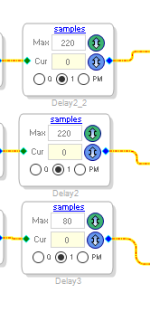
This module is necessary for adjusting the synchronicity of the three speakers at the listening point. As a rule, the signal from the LF speaker lags in time behind the signal from the HF and MF speaker. Therefore, if you want to achieve synchronous operation of the speakers at the listening point, you need to introduce a time delay in the MF and HF channel. As they say - to align the acoustic centers of the speakers.
If a phase-linear crossover is used for frequency division, you can adjust the acoustic centers relatively easily by measuring the amplitude phase response of the speaker system at the listening point while observing the step response of the measured amplitude phase response.
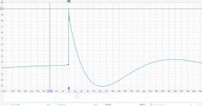
After we have adjusted the frequencies and the slope of the crossover, we measure the amplitude phase response at the listening point and observe such a step response, as we see from the picture, three maxima from three speakers are at different distances from each other on the time scale, this means that the signal from three speakers arrives at the listening point at different times.
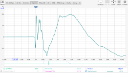
By introducing a delay in the midrange and high-frequency bands, we see in the measurements how the maxima approach each other.
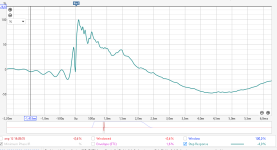
And at a certain value of delays, we get a step response that has one common maximum.
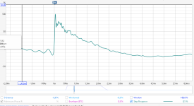
Also, the inversion of the speaker is clearly visible on the step response, if the speaker is connected in inverse polarity, then its maximum on the step response will be turned down.
The low-frequency delay module is installed for possible correction of the low-frequency channel delay between two speakers during fine-tuning of the joint operation of two three-band speakers.

This module is necessary for adjusting the synchronicity of the three speakers at the listening point. As a rule, the signal from the LF speaker lags in time behind the signal from the HF and MF speaker. Therefore, if you want to achieve synchronous operation of the speakers at the listening point, you need to introduce a time delay in the MF and HF channel. As they say - to align the acoustic centers of the speakers.
If a phase-linear crossover is used for frequency division, you can adjust the acoustic centers relatively easily by measuring the amplitude phase response of the speaker system at the listening point while observing the step response of the measured amplitude phase response.
After we have adjusted the frequencies and the slope of the crossover, we measure the amplitude phase response at the listening point and observe such a step response, as we see from the picture, three maxima from three speakers are at different distances from each other on the time scale, this means that the signal from three speakers arrives at the listening point at different times.

By introducing a delay in the midrange and high-frequency bands, we see in the measurements how the maxima approach each other.

And at a certain value of delays, we get a step response that has one common maximum.

Also, the inversion of the speaker is clearly visible on the step response, if the speaker is connected in inverse polarity, then its maximum on the step response will be turned down.
The low-frequency delay module is installed for possible correction of the low-frequency channel delay between two speakers during fine-tuning of the joint operation of two three-band speakers.
Next, mute blocks are installed, which allow you to quickly turn off the signal passing through the band.
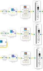
Next, there are modules for adjusting the signal level in the band.
If we need to coordinate the SPL level of the speakers in each band, this is done by entering the required level of signal level reduction in this module. In this project, you can only use a decrease in the signal level, since increasing the signal level will lead to clipping of the signal at maximum input volume.
In order not to overload the DAC input with a high output signal from the ADAU1452, you need to monitor the maximum signal level that the ADAU1452 can produce with a maximum input signal. To prevent accidental overload of the DAC input when setting up the project, a signal level limiter is installed after the amplification modules.
When entering a corrective frequency response, it is not always convenient to obtain a corrective frequency response without amplification. An example of such a case.
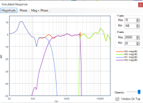
From the graphs it is clear that at an input signal frequency of 40 Hz with a level of -10 db (Fs) a signal cut off in level will appear at the DAC input; to eliminate clipping it is enough to reduce the signal level by -10 dB in all three bands using the gain block.
If you want to have a stable result with the entire range of the amplifier's output power, you need to monitor the level of the maximum output signal from the ADAU1452 that goes to the DAC input. If you feed a signal of more than 0 dB to the DAC (removing the level limiter block), then the overload protection will start to work and the speakers may produce sound that should not be there. The amplifier itself will not burn out, but you can hear very unpleasant sound combinations.

Next, there are modules for adjusting the signal level in the band.
If we need to coordinate the SPL level of the speakers in each band, this is done by entering the required level of signal level reduction in this module. In this project, you can only use a decrease in the signal level, since increasing the signal level will lead to clipping of the signal at maximum input volume.
In order not to overload the DAC input with a high output signal from the ADAU1452, you need to monitor the maximum signal level that the ADAU1452 can produce with a maximum input signal. To prevent accidental overload of the DAC input when setting up the project, a signal level limiter is installed after the amplification modules.
When entering a corrective frequency response, it is not always convenient to obtain a corrective frequency response without amplification. An example of such a case.

From the graphs it is clear that at an input signal frequency of 40 Hz with a level of -10 db (Fs) a signal cut off in level will appear at the DAC input; to eliminate clipping it is enough to reduce the signal level by -10 dB in all three bands using the gain block.
If you want to have a stable result with the entire range of the amplifier's output power, you need to monitor the level of the maximum output signal from the ADAU1452 that goes to the DAC input. If you feed a signal of more than 0 dB to the DAC (removing the level limiter block), then the overload protection will start to work and the speakers may produce sound that should not be there. The amplifier itself will not burn out, but you can hear very unpleasant sound combinations.
After the level indicator there is a DC filter and after it the signal goes to the ASRC to convert the signal into the optimal format for the DAC.
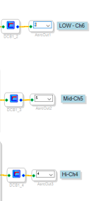
In fact, the input of the output ASRC is the end of the structural diagram in the Sigma Studio, the rest of the work is done by the hardware part of the ADAU1452 and the DAC chip.
The outputs on the amplifier board are numbered according to the ASRC channel number. The signal that is fed to input 6 of the ASRC will be present at the amplifier output under the name Ch6.
If desired, you can specify a different output number for the low-frequency band. For example, you can assign a low-frequency band to pin 5. But for this to be possible, you must first assign a different number to pin five, so that number five appears in the list of available free channels.
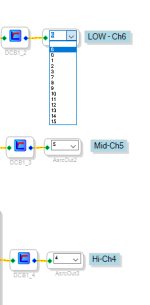
It should be noted that in this example the left channel of the stereo signal is processed. To process the right channel, you need to switch the conductor to the right channel at this point.
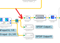
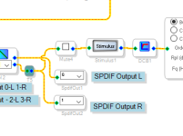
This is the main functional purpose of the blocks of the starting project for an active three-band speaker system with a FIR crossover.

In fact, the input of the output ASRC is the end of the structural diagram in the Sigma Studio, the rest of the work is done by the hardware part of the ADAU1452 and the DAC chip.
The outputs on the amplifier board are numbered according to the ASRC channel number. The signal that is fed to input 6 of the ASRC will be present at the amplifier output under the name Ch6.
If desired, you can specify a different output number for the low-frequency band. For example, you can assign a low-frequency band to pin 5. But for this to be possible, you must first assign a different number to pin five, so that number five appears in the list of available free channels.

It should be noted that in this example the left channel of the stereo signal is processed. To process the right channel, you need to switch the conductor to the right channel at this point.


This is the main functional purpose of the blocks of the starting project for an active three-band speaker system with a FIR crossover.
In the project for a three-way speaker system called I2S 3Way IIR 48kHz, a library crossover is used to divide the bands. All other blocks of the project are the same as the I2S 3Way FIR 48kHz project.
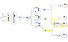
The library crossover allows you to very easily configure the crossover parameters, and it is interactive - all changes in the crossover settings are automatically transferred to the ADAU1452 and are heard in the speaker system if a music signal is fed to the board input.
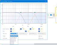
It should also be taken into account that when using an IIR crossover, the ability to align the acoustic centers of the speakers by step response becomes impossible. When using an IIR crossover, you should monitor the in-phase of the bands; it is impossible to achieve synchronicity in IIR filters. If an IIR filter is needed in the crossover that takes into account the features of the speaker radiation phase, then for each band you will have to use an IIR filter in which you can specify its quality factor and the amount of signal gain. The required IIR crossover filter settings are found using third-party CAD software and speaker measurements.

The library crossover allows you to very easily configure the crossover parameters, and it is interactive - all changes in the crossover settings are automatically transferred to the ADAU1452 and are heard in the speaker system if a music signal is fed to the board input.

It should also be taken into account that when using an IIR crossover, the ability to align the acoustic centers of the speakers by step response becomes impossible. When using an IIR crossover, you should monitor the in-phase of the bands; it is impossible to achieve synchronicity in IIR filters. If an IIR filter is needed in the crossover that takes into account the features of the speaker radiation phase, then for each band you will have to use an IIR filter in which you can specify its quality factor and the amount of signal gain. The required IIR crossover filter settings are found using third-party CAD software and speaker measurements.
In the project called I2S 3Way subtractive 48kHz, an IIR subtractive filter is implemented using a 4th order Butterworth IIR filter.
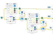
The principle of operation of such a filter is relatively simple, after the signal has passed through the low-pass filter, this filtered signal is subtracted from the input common signal, for subtraction, an inversion of the filtered signal and a delay unit are required that compensates for the delay of the low-pass filter.
The resulting frequency response can be observed in the probe window after pressing the stimulus button.
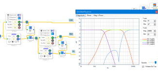
The subtractive filter allows you to get a phase-linear crossover characteristic when using IIR filtering. This allows you to use step response when adjusting the acoustic centers of the speakers and reduce the time delay for the crossover compared to the FIR crossover.

The principle of operation of such a filter is relatively simple, after the signal has passed through the low-pass filter, this filtered signal is subtracted from the input common signal, for subtraction, an inversion of the filtered signal and a delay unit are required that compensates for the delay of the low-pass filter.
The resulting frequency response can be observed in the probe window after pressing the stimulus button.

The subtractive filter allows you to get a phase-linear crossover characteristic when using IIR filtering. This allows you to use step response when adjusting the acoustic centers of the speakers and reduce the time delay for the crossover compared to the FIR crossover.

The project called Tube is intended for those who want to get distortions similar to a tube amplifier in their passive stereo system.
In this project, the level of nonlinear distortions on the left and right channels of the amplifier is adjusted from 0.005% to 15% using an external potentiometer.
The design of the project introduces distortions according to this principle:
- When changing frequency, the set level of distortion is almost the same for any frequency;
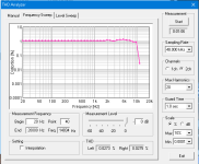
- As the signal level decreases, distortion increases;
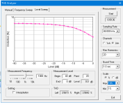
- Even harmonics prevail over odd ones.
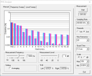
In this project, the level of nonlinear distortions on the left and right channels of the amplifier is adjusted from 0.005% to 15% using an external potentiometer.
The design of the project introduces distortions according to this principle:
- When changing frequency, the set level of distortion is almost the same for any frequency;

- As the signal level decreases, distortion increases;

- Even harmonics prevail over odd ones.

You specified these parameters in post #2 :
Performance parameter PWM DAC:
Performance parameter PWM DAC:
- Output power: 100 W per channel, with a 32 V supply and R load = 4 Ohms.
- Speaker impedance: 4 - 8 Ohm (2Ohm – max 50W)
The output LPF choke holds 6.5A, with a load of 2 Ohm, the peak power at which the choke will be saturated will be approximately equal to 6.5A * 6.5A * 2R = 84W. The average power will be approximately 84/2 = 42W. According to measurements, the current protection in the TAS starts to operate at an average power of 50W with a load of 2 Ohm.Could you explain the 2 Ohm limit?
Simply put, in this case, in this implementation, the limitation is in the saturation current of the choke, and not in the TAS.
Since this board was developed for home active speakers, which usually use 4 Ohm and 8 Ohm speakers, then 2 Ohm, which are usually used in cars, were not a priority.
If I set it to 12A inductance, the dimensions of the board will increase and the price too. I chose smaller dimensions and lower cost.
By the way.
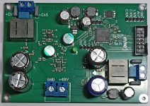
Just today I took measurements from a 2-channel DSP Amp at 200W per channel on TAS5162. It has high-current chokes and these boards can already handle 200W at 2 Ohm.
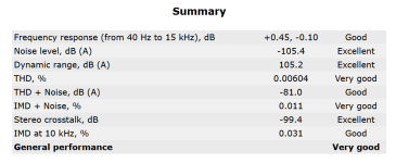
Below are the measurement results for a 4 Ohm load.
I'm thinking of creating a new branch for these boards, their power is neither here nor there, it's hard to say whether there will be interest in them.
Thanks for the explanation. In my case I have a 3-way with two 4 ohm woofers. So I'm limited to either a 8 ohm (series) or 2 ohm (parallel) load. It seems to me the series configuration is the better way to go.
Pout=(Vout rms*Vout rms)/R If at a load of 4 Ohm we have 100 W, then with an increase in load resistance the consumed power will decrease proportionally according to the formula. That is, at 8 Ohm the power will be 50 W.How much power can be expected with an 8 ohm load, about 3x 60W?
And about 3x 75W on 3 ohms?
At a 3 Ohm load, the saturation current limitations of the choke start to come into effect. If we know that the maximum power at 2 Ohm is 50 W, and at a 4 Ohm load the power is 100 W, then we can find the power at a 3 Ohm load through interpolation. Most likely, at a 3 Ohm load the maximum power will be 75 W.
In such amplifiers, the output power is limited by the power supply voltage and the saturation current of the output choke.
In order for the output signal to be undistorted, a reserve is needed both for current and voltage. I configured the DAC output so that with an input signal of 0 dB (Fs) it would produce an amplitude voltage of 28.3 V, which is equal to 20 V RMS.
But all this is true for a supply voltage of 32 V. If there is no need to get 100W from the DAC, and you want to reduce the heating of the board, then you can supply 24V to the DAC, thereby reducing the maximum output power to 50W per channel, but in this case the DAC output can already be overloaded by the input signal, to avoid overloading the DAC, you need to reduce the gain in each band by 3 dB in the ADAU1452.
32V / 24V = 1.33 times, reducing the gain in each band by 3 dB is equivalent to reducing the supply voltage by 1.41 times. If we supply 12V to the board, you need to reduce the gain by 6 dB. Reducing the gain in the channel will save the DAC output from clipping the output signal at a maximum input signal level of 0 db (Fs).
Hi , Uriy - nice project , congrats. I have a few queries.
1) Did you consider using link play modules and 4stream app
2) I am using Linkplay + Arylic only for the APP UI and ease of Wifi connections - setup etc + stability. However I am sure the audio quality of your project is far better due to difference in DSP , my query how much difference would you benchmark in percentage in setup of LMS to Linkplay + 4 stream app, UI and stability.
I have not considered such modules. But I do not see any problems to connect such a module to my board. The Link Play A31 board has a 5V supply and has an I2S output. My board has a 5V output and an I2S input, ADAU1452 accepts I2S via ASRC, so there is no need to synchronize frequencies between Link Play A31 and ADAU1452. It will work.1) Did you consider using link play modules and 4stream app
As I understand it, Arylic uses the TPA3116 chip in its amplifiers, so they need to use a DAC, and the TPA3116 itself cannot show the level of nonlinear distortion that my board can handle. Therefore, the problem is not in the quality of the DSP, but in the quality of the power amplifiers.However I am sure the audio quality of your project is far better due to difference in DSP
I can't give you an answer. I haven't used Linkplay + 4 stream app. I can't compare. I think you can find this answer on the LMS forum.my query how much difference would you benchmark in percentage in setup of LMS to Linkplay + 4 stream app, UI and stability.
I have an LMS server on my computer, I use streaming, I listen to the radio from the Internet. If the Internet connection is stable, then there are no problems with streaming. In my little experience, LMS and Squeezelite-esp32 are quite stable solutions. Also, Squeezelite-esp32 is open source, has a simple firmware update via the web interface, and anyone can add a display to the board or control buttons, I specifically made the output of ports for this, so I don't see the reasons in considering other streaming solutions.
Hi Uriy, Thanks for your replies - just one update - Arylic uses a DSP it is this - MVSILICON BP1064A2 (and it cannot be compared to ADAU) + they have a ESS ES9023 DAC board tt I have used , will send some pictures. LMS is it only web based or there is an app.As I understand it, Arylic uses the TPA3116 chip in its amplifiers, so they need to use a DAC, and the TPA3116 itself cannot show the level of nonlinear distortion that my board can handle. Therefore, the problem is not in the quality of the DSP, but in the quality of the power amplifiers.
Lyrion Music Server - LMS.LMS is it only web based or there is an app.
Please read the message in this thread under #10.
I want to thank you for the excellent information presented here. I'm developing a crossover using this DSP and it seems to be more powerful than I thought!
WROVER modules contain the squeezelite-esp32 program, which allows you to stream music via Wi-Fi using LMS.
squeezelite-esp32 also allows you to update yourself via Wi-Fi and a web interface.
To update squeezelite-esp32, you need to enter the squeezelite-esp32 IP address in the address bar of your Internet browser. We received the IP address when registering squeezelite-esp32 in a Wi-Fi network. If we don’t remember the IP address, we can find it in the LMS server settings when squeezelite-esp32 is connected to it, as shown in post number 10 in this topic.
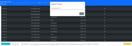
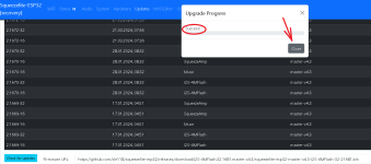
After we go to the squeezelite-esp32 control web page, we need to go to the Updates tab and select the update we want to add to WROVER. Any firmware with the I2S-4MFlash prefix is suitable for this input board.

After selecting the desired firmware, you need to click the Flash Firmware button and wait for the program update to complete.


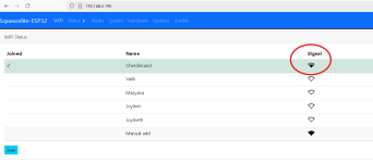
For stable operation of streaming from the Internet, at least two conditions are required, the first condition is a good connection of WROVER with a local Wi-Fi network, the signal level can be seen in this tab. If we see a low signal level, then we need to connect an external antenna to the module, for which a connector is provided on the WROVER board.
The second condition is a stable Internet connection, which must already be checked using other test programs.
If we have an unstable connection in the local Wi-Fi network when playing music from a computer or smartphone, then most likely we have a weak signal between WROVER and the Wi-Fi router. The stability of the WROVER connection with Wi-Fi is clearly visible in this window.

squeezelite-esp32 also allows you to update yourself via Wi-Fi and a web interface.
To update squeezelite-esp32, you need to enter the squeezelite-esp32 IP address in the address bar of your Internet browser. We received the IP address when registering squeezelite-esp32 in a Wi-Fi network. If we don’t remember the IP address, we can find it in the LMS server settings when squeezelite-esp32 is connected to it, as shown in post number 10 in this topic.
After we go to the squeezelite-esp32 control web page, we need to go to the Updates tab and select the update we want to add to WROVER. Any firmware with the I2S-4MFlash prefix is suitable for this input board.


After selecting the desired firmware, you need to click the Flash Firmware button and wait for the program update to complete.


For stable operation of streaming from the Internet, at least two conditions are required, the first condition is a good connection of WROVER with a local Wi-Fi network, the signal level can be seen in this tab. If we see a low signal level, then we need to connect an external antenna to the module, for which a connector is provided on the WROVER board.

The second condition is a stable Internet connection, which must already be checked using other test programs.
If we have an unstable connection in the local Wi-Fi network when playing music from a computer or smartphone, then most likely we have a weak signal between WROVER and the Wi-Fi router. The stability of the WROVER connection with Wi-Fi is clearly visible in this window.

Have been debating whether to go passive or active on a 3-way design, but couldn't find an amplifier solution I liked. This is seriously tipping me toward active with your boards.
The price and availability of the boards can be found in this topic.
https://www.diyaudio.com/community/threads/board-3-way-dsp-amp.415079/
https://www.diyaudio.com/community/threads/board-3-way-dsp-amp.415079/
- Home
- Amplifiers
- Class D
- 3 Way DSP Amp
