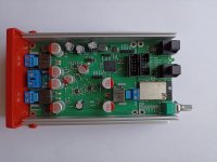
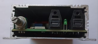
I assembled the following revision of the light version of the board, three channels of 100W PWM DAC with DSP ADAU1452.
Since there were some changes to the board structure, I decided to create a new topic to avoid confusion. Description of the previous version of the board here.
On this board revision, I add three auxiliary ADC inputs and two discrete input/output ports from the DSP. This expands the possibilities of external control of the chipboard.
To coordinate the operation of the ESP32 module and the DSP via the I2S port, a clock frequency detection circuit was implemented on the I2S bus; this was done to eliminate the transient process when receiving I2S data.

An ESP32 module was added to the optical input/output board to implement wireless audio transmission via Wi-Fi and Bluetooth.


Starter projects for Sigma Studio.
Since there were some changes to the board structure, I decided to create a new topic to avoid confusion. Description of the previous version of the board here.
On this board revision, I add three auxiliary ADC inputs and two discrete input/output ports from the DSP. This expands the possibilities of external control of the chipboard.
To coordinate the operation of the ESP32 module and the DSP via the I2S port, a clock frequency detection circuit was implemented on the I2S bus; this was done to eliminate the transient process when receiving I2S data.
An ESP32 module was added to the optical input/output board to implement wireless audio transmission via Wi-Fi and Bluetooth.
Starter projects for Sigma Studio.
Attachments
Last edited:
Performance parameter PWM DAC:


High performance output of the PWM DAC is achieved through the use of an individual power stage of the TAS5352 type for each channel, and the coverage each channel of enhanced PWM feedback.
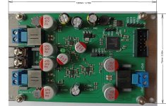
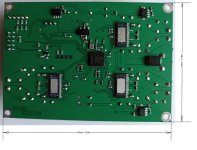
The power stage of the TAS5352 includes protection against low supply voltage, overheating, and output overload. The output of the TAS5352 is connected in a bridge PBTL configuration, which eliminates the possibility of abnormal DC voltage appearing at the DAC output. In case of a TAS5352 failure, it will short the power supply pole, triggering the protection in the power supply unit.
The output PWM DAC has no voltage spikes at its output when the power is turned on and off.
To enable external volume control, the auxiliary input of the ADC0 DPS and an external potentimeter are used.
The PWM DAC chip monitors the presence of a DC offset at the output of each channel and disables the channel if it is present. The PWM DAC does not require external additional speaker protection circuits from DC.
For programming the DSP of the board, a USBi programmer and the free development environment SigmaStudio are required. The board comes with a basic DSP configuration that allows using the board as a stereo amplifier with a third low-frequency channel for a subwoofer.
Auxiliary ADCs allow you to adjust the DSP settings using external potentiometers; for example, using potentiometers you can implement a tone control. Discrete ports allow you to connect a rotary encoder for digital volume control in a DSP, or you can control software switches to quickly switch between modules in a Sigma Studio project.
- Output power: 100 W per channel, with a 32 V supply and R load = 4 Ohms.
- Speaker impedance: 4 - 8 Ohm (2Ohm – max 50W)
- Frequency response: 20Hz - 20kHz
- THD: less than 0.005% on 8Ohm load, and less than 0.01% on 4Ohm load
- SNR: 106dB(A)
- Spdif Input : 16-32bit 44.1-96kHz
- Spdif Output : 16-32bit 44.1-96kHz
- I2S Input : 16-32bit 44.1-192kHz
- Power supply: DC 12V - 32V/ 5A-10A
- Consumption power: Idle mode 10W, sleeping mode 2.5W
- Efficiency - 80%
High performance output of the PWM DAC is achieved through the use of an individual power stage of the TAS5352 type for each channel, and the coverage each channel of enhanced PWM feedback.


The power stage of the TAS5352 includes protection against low supply voltage, overheating, and output overload. The output of the TAS5352 is connected in a bridge PBTL configuration, which eliminates the possibility of abnormal DC voltage appearing at the DAC output. In case of a TAS5352 failure, it will short the power supply pole, triggering the protection in the power supply unit.
The output PWM DAC has no voltage spikes at its output when the power is turned on and off.
To enable external volume control, the auxiliary input of the ADC0 DPS and an external potentimeter are used.
The PWM DAC chip monitors the presence of a DC offset at the output of each channel and disables the channel if it is present. The PWM DAC does not require external additional speaker protection circuits from DC.
For programming the DSP of the board, a USBi programmer and the free development environment SigmaStudio are required. The board comes with a basic DSP configuration that allows using the board as a stereo amplifier with a third low-frequency channel for a subwoofer.
Auxiliary ADCs allow you to adjust the DSP settings using external potentiometers; for example, using potentiometers you can implement a tone control. Discrete ports allow you to connect a rotary encoder for digital volume control in a DSP, or you can control software switches to quickly switch between modules in a Sigma Studio project.
The WROVER V4 module was added to the optical SPDIF input/output board. The WROVER module is programmed with Squeezelite-esp32, a 32-bit version of I2S-4MFlash, which allows audio to be transmitted 24-bit.
Details of the capabilities of this program are described here.
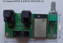
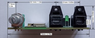
Squeezelite-esp32 is a well-developed program that allows you to manage WROVER settings via a web interface. The Squeezelite-esp32 program is updated via a web interface over the air.
When power is supplied to the input-output board, Squeezelite-esp32 will request registration in the Wi-Fi network, password "Squeezelite", after registering Squeezelite-esp32 on the network, Squeezelite will show the IP address, by going to the specified IP address you can manage the settings and update the Squeezelite-esp32 program.
Using an LMS, you can organize streaming both from the Internet and from local music storage.
To coordinate the operation of the DAC board and WROVER via I2S, a bit clock frequency detector was added to the DAC board, when Squeezelite does not receive music over the air, it supports a logical low level at the I2S output, the frequency detector at the MP11 input supports a logical hi level, the DSP switch is connected to the spdif input, as soon as a logical low level appears on MP11, the DSP will switch its input to I2S. This eliminates clicks when I2S appears, and in this way automatic switching of inputs is achieved, priority is on the I2S input, when there is a signal at the I2S input, the DSP is connected to the I2S input.
Details of the capabilities of this program are described here.


Squeezelite-esp32 is a well-developed program that allows you to manage WROVER settings via a web interface. The Squeezelite-esp32 program is updated via a web interface over the air.
When power is supplied to the input-output board, Squeezelite-esp32 will request registration in the Wi-Fi network, password "Squeezelite", after registering Squeezelite-esp32 on the network, Squeezelite will show the IP address, by going to the specified IP address you can manage the settings and update the Squeezelite-esp32 program.
Using an LMS, you can organize streaming both from the Internet and from local music storage.
To coordinate the operation of the DAC board and WROVER via I2S, a bit clock frequency detector was added to the DAC board, when Squeezelite does not receive music over the air, it supports a logical low level at the I2S output, the frequency detector at the MP11 input supports a logical hi level, the DSP switch is connected to the spdif input, as soon as a logical low level appears on MP11, the DSP will switch its input to I2S. This eliminates clicks when I2S appears, and in this way automatic switching of inputs is achieved, priority is on the I2S input, when there is a signal at the I2S input, the DSP is connected to the I2S input.
Last edited:
For anyone interested in using a similar solution in their developments, I created a thread about the price and availability of these boards.
https://www.diyaudio.com/community/threads/board-3-way-dsp-amp.415079/
https://www.diyaudio.com/community/threads/board-3-way-dsp-amp.415079/
The amplifier board is installed on an aluminum plate measuring 120mm/72mm, this plate is not a radiator, but a heat conductor for attaching the board to a large radiator, the consumption of the board in active mode is 10W with a 32V power supply. When operating the amplifier at maximum power on a high-density music signal such as rock, the effective cooling area of the external passive radiator must be at least 400 square centimeters.
However, when there is no need for high output power, the board’s supply voltage can be reduced to 12V; when the board is powered from 12V, it will not be able to output 100W at 4 Ohms, but the board’s consumption will be at a level at which the area of the heat conductor plate will be sufficient to cool the microcircuits. To ensure that the DAC output signal does not get clipped when the maximum volume is applied to the DSP input, you need to set the signal suppression to -9 dB in the Sigma Studio project and then the DAC output will not clip the signal at full input volume. It is also very convenient to configure the project on a low supply voltage of the board, thereby eliminating unexpected loud effects from the speakers in the event of erroneous actions with the program in Sigma Studio.
However, when there is no need for high output power, the board’s supply voltage can be reduced to 12V; when the board is powered from 12V, it will not be able to output 100W at 4 Ohms, but the board’s consumption will be at a level at which the area of the heat conductor plate will be sufficient to cool the microcircuits. To ensure that the DAC output signal does not get clipped when the maximum volume is applied to the DSP input, you need to set the signal suppression to -9 dB in the Sigma Studio project and then the DAC output will not clip the signal at full input volume. It is also very convenient to configure the project on a low supply voltage of the board, thereby eliminating unexpected loud effects from the speakers in the event of erroneous actions with the program in Sigma Studio.
I posted the boards on eBay.
Link to the board. https://www.ebay.com/itm/395575382975
Link to the board plus the input/output board. https://www.ebay.com/itm/395575405136
Who wants it a little cheaper. https://www.diyaudio.com/community/threads/board-3-way-dsp-amp.415079/
Link to the board. https://www.ebay.com/itm/395575382975
Link to the board plus the input/output board. https://www.ebay.com/itm/395575405136
Who wants it a little cheaper. https://www.diyaudio.com/community/threads/board-3-way-dsp-amp.415079/
To implement an active three-band stereo system that receives sound via a radio channel, for good channel synchronization, it is necessary to transmit sound from the DSP core to the slave speaker system.
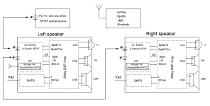
When receiving and transmitting a signal by the DSP core, a time delay of 1.1 ms occurs, which must be taken into account, you just need to add a delay to the channel that we allocate as a master.

Below I have attached project files in Sigma Studio as an example of introducing this delay to compensate for the time delay of the channels.
In the example, the left channel is the master.
Note that in this example, the volume is adjusted by an external potentiometer in both channels equally. Well, if you need to make the right channel the master and the left one slave, then you just need to reassign the delay block from T1 to T5, and on the slave channel, switch the input from 1 to 0.

When receiving and transmitting a signal by the DSP core, a time delay of 1.1 ms occurs, which must be taken into account, you just need to add a delay to the channel that we allocate as a master.

Below I have attached project files in Sigma Studio as an example of introducing this delay to compensate for the time delay of the channels.
In the example, the left channel is the master.
Note that in this example, the volume is adjusted by an external potentiometer in both channels equally. Well, if you need to make the right channel the master and the left one slave, then you just need to reassign the delay block from T1 to T5, and on the slave channel, switch the input from 1 to 0.
Attachments
Last edited:
Based on this board, it is quite easy to implement a stereo system plus a low-frequency channel.
The starting project for sigma studio is in the folder attached to the first post, called - 2+1.


It should be understood that simply connecting the speakers to the board, in very rare cases, will immediately show a high result.
To get a good result, it is necessary to configure each channel for specific speakers and a specific acoustic environment.
It is necessary to configure the system using microphone measurements. With the help of a microphone, optimal frequencies are found for the speakers to operate, and the microphone is also used to correct the influence of the room on the speaker system. Only after individual adjustment of each speaker, you will be able to hear a good result, provided that the speaker does not have increased nonlinear distortions in the range of frequencies and powers at which you operate them.
Nonlinear distortions of the board itself specified in the characteristics decrease with a decrease in output power, and at an acceptable volume for listening are in the range of 0.003%. Which is quite enough to obtain a completely acceptable result sound for a not very sophisticated ear.

The starting project for sigma studio is in the folder attached to the first post, called - 2+1.
It should be understood that simply connecting the speakers to the board, in very rare cases, will immediately show a high result.
To get a good result, it is necessary to configure each channel for specific speakers and a specific acoustic environment.
It is necessary to configure the system using microphone measurements. With the help of a microphone, optimal frequencies are found for the speakers to operate, and the microphone is also used to correct the influence of the room on the speaker system. Only after individual adjustment of each speaker, you will be able to hear a good result, provided that the speaker does not have increased nonlinear distortions in the range of frequencies and powers at which you operate them.
Nonlinear distortions of the board itself specified in the characteristics decrease with a decrease in output power, and at an acceptable volume for listening are in the range of 0.003%. Which is quite enough to obtain a completely acceptable result sound for a not very sophisticated ear.
Last edited:
To implement the streaming music on the input board in ESP32, a program called Squeezelite-ESP32 is flashed, 32-bit version I2S-4MFlash.32 which allows you to transmit 24 bits to the I2S port. More details about the capabilities of this program can be found here.
https://github.com/sle118/squeezelite-esp32?tab=readme-ov-file#spotify
When you apply power to the input board, a new WiFi network named Squeezelite will appear in the WiFi network. When you connect to this network from your smartphone, this network will ask for a password, the login password is - squeezelite. When you enter the "Squeezlite" network, Squeezelite will ask you to specify your home WiFi network and specify the password for your home WiFi network. When you specify the home WiFi network settings, Squeezelite will automatically register with it and show you its registration IP address. After registration, you will no longer see the Squeezelite WiFi network, since the module will automatically connect to your network the next time you power it on.
Knowing the IP address, you can go to this IP from any browser and get access to managing and updating Squeezelite-ESP32.
This program has a fairly advanced web interface for managing ESP32. To get to the ESP32 control interface, you need to enter the IP address in the browser address bar, and you will be taken to the ESP32 module control and configuration pages. On these pages, you can see the current state of the module, and you can also check and update the Squeezelite firmware over the air. To access the settings, the ESP32 must be turned on and registered in your WiFi network.
I have configured the basic necessary functions of the board and it does not require additional configuration.
To register the Squeezelite-ESP32 in a new WiFi network, it is enough that the input board does not see the previous WiFi network.
For those who want to register the Squeezelite-ESP32 in their network using a computer, there is a video that shows everything well, what to click where when first registering the Squeezelite-ESP32 in a WiFi network.
To organize audio transmission via Wi-Fi using the Squeezelite-ESP32 program, you need to install the LMS program on your computer. It will allow you to organize audio transmission both from the Internet and from local storage. LMS also allows you to adjust the volume level and turn the sound on and off at the ESP32 output via WiFi. The LMS program can be downloaded from here.
https://lyrion.org/getting-started/
LMS can be installed on Android, thus eliminating the need for a constantly turned on computer, i.e. managing streaming from Android. Here is how to install LMS on Android.
https://forums.slimdevices.com/foru...announcement-running-lms-on-an-android-device
For those who use Spotify, there is an instruction on how to launch it using LMS.
https://www.max2play.com/en/how-tos/howto-spotify/#:~:text=Use Spotify Connect function,time via „Available Devices“
The IP address that we learned when registering Squeezelite in our WiFi network can change automatically. And if suddenly you cannot access the Squeezelite settings using the old IP address that we learned earlier, then the new IP address can be found in the LMS server settings when the server connects Squeezelite to itself. In this window, we can see that the server has connected Squeezelite to itself.
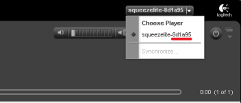
Pay attention to the last six characters, they correspond to the last six characters of the Squeezelite MAC address.
In the LMS settings, in the information tab, we can find out the IP address of the input board in order to access the Squeezelite program settings.
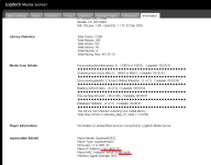
After we find out the IP address, we enter it in the browser address bar and get access to the Squeezelite program settings.

https://github.com/sle118/squeezelite-esp32?tab=readme-ov-file#spotify
When you apply power to the input board, a new WiFi network named Squeezelite will appear in the WiFi network. When you connect to this network from your smartphone, this network will ask for a password, the login password is - squeezelite. When you enter the "Squeezlite" network, Squeezelite will ask you to specify your home WiFi network and specify the password for your home WiFi network. When you specify the home WiFi network settings, Squeezelite will automatically register with it and show you its registration IP address. After registration, you will no longer see the Squeezelite WiFi network, since the module will automatically connect to your network the next time you power it on.
Knowing the IP address, you can go to this IP from any browser and get access to managing and updating Squeezelite-ESP32.
This program has a fairly advanced web interface for managing ESP32. To get to the ESP32 control interface, you need to enter the IP address in the browser address bar, and you will be taken to the ESP32 module control and configuration pages. On these pages, you can see the current state of the module, and you can also check and update the Squeezelite firmware over the air. To access the settings, the ESP32 must be turned on and registered in your WiFi network.
I have configured the basic necessary functions of the board and it does not require additional configuration.
To register the Squeezelite-ESP32 in a new WiFi network, it is enough that the input board does not see the previous WiFi network.
For those who want to register the Squeezelite-ESP32 in their network using a computer, there is a video that shows everything well, what to click where when first registering the Squeezelite-ESP32 in a WiFi network.
To organize audio transmission via Wi-Fi using the Squeezelite-ESP32 program, you need to install the LMS program on your computer. It will allow you to organize audio transmission both from the Internet and from local storage. LMS also allows you to adjust the volume level and turn the sound on and off at the ESP32 output via WiFi. The LMS program can be downloaded from here.
https://lyrion.org/getting-started/
LMS can be installed on Android, thus eliminating the need for a constantly turned on computer, i.e. managing streaming from Android. Here is how to install LMS on Android.
https://forums.slimdevices.com/foru...announcement-running-lms-on-an-android-device
For those who use Spotify, there is an instruction on how to launch it using LMS.
https://www.max2play.com/en/how-tos/howto-spotify/#:~:text=Use Spotify Connect function,time via „Available Devices“
The IP address that we learned when registering Squeezelite in our WiFi network can change automatically. And if suddenly you cannot access the Squeezelite settings using the old IP address that we learned earlier, then the new IP address can be found in the LMS server settings when the server connects Squeezelite to itself. In this window, we can see that the server has connected Squeezelite to itself.

Pay attention to the last six characters, they correspond to the last six characters of the Squeezelite MAC address.
In the LMS settings, in the information tab, we can find out the IP address of the input board in order to access the Squeezelite program settings.

After we find out the IP address, we enter it in the browser address bar and get access to the Squeezelite program settings.

Last edited:
For the case when you need to have remote volume control, I assembled a circuit that simulates the operation of a potentiometer based on a microcontroller.
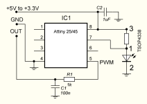
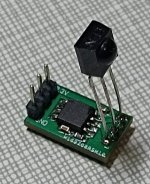
The microcontroller receives a signal from the remote control and generates a PWM signal, which is converted into a constant voltage using an RC circuit, which in turn can be fed to the input of the auxiliary ADC in the ADAU1452.
The board's pins are matched to the potentiometer pins on the input board, and this receiver can be installed in place of the potentiometer on the input board. The receiver can operate from both 3.3V and 5V, which allows it to be connected to other ADC ports using the 5V power supplied to the ADC input pins.
The volume level is saved in the microcontroller's eeprom after half a minute if the volume level has been changed. If the volume level has not changed, then no recording is made in the eeprom.
The receiver is configured to encode remote controls from LG TVs.
If desired and possible, the encoding to which the receiver responds can be changed for your remote control by making the appropriate changes to the program that I attached to the message. The program for the microcontroller is written in Atmel Studio 7. The program works quite simply, when the level at input 7 falls, an interrupt is triggered and the timer starts counting the time, after the second fall, the timer readings are recorded and the timer is reset, based on the time that has passed between the two falls, the preamble and subsequent reception of zeros or ones are determined, since in the signal transmission transaction the duration of zero is less than the duration of one, then it is very easy to form the received number, then the number is compared inside the program and a decision is made about the increment or decrement of the PWM signal at pin 5. To save space in the microcontroller's memory, the program does not remember all 32 bits of the code package, it records the last 16 bits, which is quite enough to recognize the type of command. When you press the mute or ON/OF button on the remote control, the PWM signal at the 5th output of the microcontroller stops; when you press these buttons again, the PWM level returns to the previous level; these commands are not saved in memory, so when you switch the power supply, the previously set volume level will be at the PWM output.
Attachments
Last edited:
For a quick start with 3Way DSP Amp boards, projects in Sigma Studio are attached to the first message.
To program the DSP ADAU1452, you need a USBi programmer that connects to the board via the I2C interface using three conductors GND, SCL, SDA. And you need a free development environment called SigmaStudio.
To connect the programmer to the board, you need to connect the conductors of the same name on the board and the programmer, GND-GND, SCL-SCL, SDA-SDA. The first conductor that connects to the board should be GND-GND.
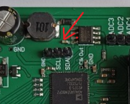
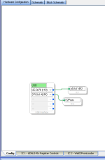
When connecting the programmer to the computer, a green indicator should appear in Sigma Studio.
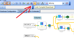
To compile the project and add it to the ADAU1452, you need to press this button.
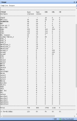
If all the conductors are connected correctly and there are no errors in the project, then the ADAU1452 will be configured according to the project. In the right window, you can see how much resource each block of the project requires.
If the programmer has no connection with ADAU1452, then after pressing the compile and download button, the following message will appear.
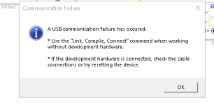
This message is displayed once and when you press the download button again, this message will not be displayed, and the project will not be loaded into ADAU1452, which sometimes leads to erroneous conclusions that your changes to the project do not lead to the expected result.
When setting up a project for constant monitoring of the ADAU1452 connection with Sigma Studio, I use a signal level indicator. I feed music to the board input and watch the indicator movement in Sigma Studio. When the connection is correct, the indicator constantly changes its value. When the connection is broken, the signal level indicator freezes, which tells me that I need to reconnect the programmer.

If an error was made in the project, then an error message will appear when compiling the project.
To program the DSP ADAU1452, you need a USBi programmer that connects to the board via the I2C interface using three conductors GND, SCL, SDA. And you need a free development environment called SigmaStudio.
To connect the programmer to the board, you need to connect the conductors of the same name on the board and the programmer, GND-GND, SCL-SCL, SDA-SDA. The first conductor that connects to the board should be GND-GND.

When connecting the programmer to the computer, a green indicator should appear in Sigma Studio.

To compile the project and add it to the ADAU1452, you need to press this button.

If all the conductors are connected correctly and there are no errors in the project, then the ADAU1452 will be configured according to the project. In the right window, you can see how much resource each block of the project requires.

If the programmer has no connection with ADAU1452, then after pressing the compile and download button, the following message will appear.

This message is displayed once and when you press the download button again, this message will not be displayed, and the project will not be loaded into ADAU1452, which sometimes leads to erroneous conclusions that your changes to the project do not lead to the expected result.
When setting up a project for constant monitoring of the ADAU1452 connection with Sigma Studio, I use a signal level indicator. I feed music to the board input and watch the indicator movement in Sigma Studio. When the connection is correct, the indicator constantly changes its value. When the connection is broken, the signal level indicator freezes, which tells me that I need to reconnect the programmer.

If an error was made in the project, then an error message will appear when compiling the project.

I will describe the purpose of the blocks using the example of the I2S 3Way FIR 48kHz project from the folder attached in the first message.
The structural diagram is long, so I will give it in two pictures.
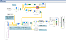
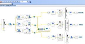
The signal passes from left to right, i.e. from the left the signal enters the structural diagram, and from the right the signal exits the structural diagram.
In order to decouple from the clock frequency of the external digital signal source, the ADAU1452 has eight Asynchronous Sample Rate Converters (ASRC). ASRC allows you to receive a digital signal with different sampling rates to the digital input of the ADAU1452 without worrying about the desynchronization of the signal and the clock frequency inside the ADAU1452. ADAU1452 uses a very good ASRC that does not introduce any changes to the signal that are noticeable in measurements.
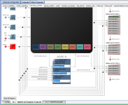
The presence of ASRC and their use in this project allows you not to worry about the sampling frequency of the signal source, this greatly simplifies the task of receiving a signal from different digital signal sources. In this project, ASRC0 is configured to receive spdif, ASRC1 is configured to receive a signal via the I2S port, ASRC2 ASRC3 is configured to transmit a signal from ADAU1452 to the input of the power DAC via the I2S protocol.
The outputs of the ASRC configured to receive a digital signal are connected to the MX1 input selector block. Using an external signal detection circuit on the BCLK wiring, an automatic selection circuit for the input signal source between the optical input and the I2S input is implemented.
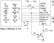
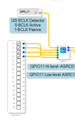
The circuit generates a logical signal at the discrete input MP11 (GPIO11), which in turn controls the stereo selector MX1. If there is no signal in the I2S bus, there is no signal on the BCLK conductor either, the transistor is closed and there is a logical one at the MP11 input. The input selector connects the spdif input signal to the signal level control block. When a signal appears on the BCLK conductor, the transistor opens and a logical one appears on the MP11 pin, which activates the input selector via the GPIO11 port and connects the I2S input to the signal level control unit. Priority is on the I2S input, as long as there is a signal on the BCLK conductor, the multiplexer will support the I2S connection. This should be taken into account if an I2S source is used that has a constant signal on the BCLK pin. The Squeezelite-ESP32 program automatically disables all signals on all I2S bus lines in the absence of a Wi-Fi signal, which allows you to get automatic switching of inputs using this circuit.
The structural diagram is long, so I will give it in two pictures.


The signal passes from left to right, i.e. from the left the signal enters the structural diagram, and from the right the signal exits the structural diagram.
In order to decouple from the clock frequency of the external digital signal source, the ADAU1452 has eight Asynchronous Sample Rate Converters (ASRC). ASRC allows you to receive a digital signal with different sampling rates to the digital input of the ADAU1452 without worrying about the desynchronization of the signal and the clock frequency inside the ADAU1452. ADAU1452 uses a very good ASRC that does not introduce any changes to the signal that are noticeable in measurements.

The presence of ASRC and their use in this project allows you not to worry about the sampling frequency of the signal source, this greatly simplifies the task of receiving a signal from different digital signal sources. In this project, ASRC0 is configured to receive spdif, ASRC1 is configured to receive a signal via the I2S port, ASRC2 ASRC3 is configured to transmit a signal from ADAU1452 to the input of the power DAC via the I2S protocol.
The outputs of the ASRC configured to receive a digital signal are connected to the MX1 input selector block. Using an external signal detection circuit on the BCLK wiring, an automatic selection circuit for the input signal source between the optical input and the I2S input is implemented.


The circuit generates a logical signal at the discrete input MP11 (GPIO11), which in turn controls the stereo selector MX1. If there is no signal in the I2S bus, there is no signal on the BCLK conductor either, the transistor is closed and there is a logical one at the MP11 input. The input selector connects the spdif input signal to the signal level control block. When a signal appears on the BCLK conductor, the transistor opens and a logical one appears on the MP11 pin, which activates the input selector via the GPIO11 port and connects the I2S input to the signal level control unit. Priority is on the I2S input, as long as there is a signal on the BCLK conductor, the multiplexer will support the I2S connection. This should be taken into account if an I2S source is used that has a constant signal on the BCLK pin. The Squeezelite-ESP32 program automatically disables all signals on all I2S bus lines in the absence of a Wi-Fi signal, which allows you to get automatic switching of inputs using this circuit.
After the input selector there is a signal level control unit.
To implement the ability to adjust the volume level using an external potentiometer, an auxiliary ADC0 is used.
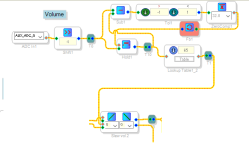
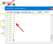
This project implements a "hysteresis" signal level control circuit to prevent noise from the ADC input from getting into the useful signal. The volume level control curve can be set independently by opening the value table window and entering your values there.
After the signal level regulator, the outputs are connected to the output port of the spdif.
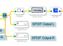
ADAU1452 allows you to output a signal via spdif from the DSP core and also allows you to copy the spdif signal from the input to the spdif output without using the DSP core. Setting up how to generate a spdif signal is performed in this window.
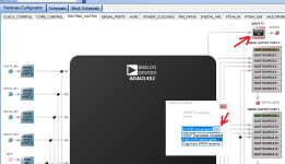
If the spdif signal is copied from the spdif input to the spdif output, then there is no delay in the signal, i.e. when copying the signal, all devices connected to the spdif will receive the signal synchronously. But if the signal in spdif is output from the DSP core, then between the spdif input signal and the spdif output signal there will be a delay of 1.1 ms, this delay is stable and can be easily taken into account when operating the boards in an active three-way stereo speaker system.
According to this scheme, volume control will be transmitted via the spdif channel to the next board, which achieves synchronous volume control in both active speakers.
To compensate for the DSP delay for synchronous operation of two speakers, the speaker that is the spdif source for the second speaker must have a signal delay module after transmitting the signal to the spdif port.
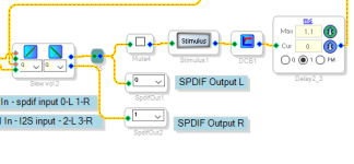
The mute4 block allows you to block the signal from passing through the circuit by checking the box.
The stimulus block is needed to activate the probe module, which I will describe later.
The DCB1 block is needed to prevent the penetration of the constant component of the signal, which may appear when the signal source fails.
To implement the ability to adjust the volume level using an external potentiometer, an auxiliary ADC0 is used.

This project implements a "hysteresis" signal level control circuit to prevent noise from the ADC input from getting into the useful signal. The volume level control curve can be set independently by opening the value table window and entering your values there.

After the signal level regulator, the outputs are connected to the output port of the spdif.

ADAU1452 allows you to output a signal via spdif from the DSP core and also allows you to copy the spdif signal from the input to the spdif output without using the DSP core. Setting up how to generate a spdif signal is performed in this window.

If the spdif signal is copied from the spdif input to the spdif output, then there is no delay in the signal, i.e. when copying the signal, all devices connected to the spdif will receive the signal synchronously. But if the signal in spdif is output from the DSP core, then between the spdif input signal and the spdif output signal there will be a delay of 1.1 ms, this delay is stable and can be easily taken into account when operating the boards in an active three-way stereo speaker system.
According to this scheme, volume control will be transmitted via the spdif channel to the next board, which achieves synchronous volume control in both active speakers.
To compensate for the DSP delay for synchronous operation of two speakers, the speaker that is the spdif source for the second speaker must have a signal delay module after transmitting the signal to the spdif port.

The mute4 block allows you to block the signal from passing through the circuit by checking the box.
The stimulus block is needed to activate the probe module, which I will describe later.
The DCB1 block is needed to prevent the penetration of the constant component of the signal, which may appear when the signal source fails.
After DCB1, a high-pass filter with a cutoff frequency of 10 Hz is installed.
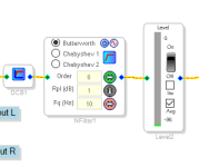
This filter is designed to cut off low frequencies that the LF speaker cannot reproduce. Cutting off low frequencies allows you to unload the LF speaker, and thereby reduce the heating and level of nonlinear distortion of this speaker. The filter cutoff frequency should be set based on the capabilities of the LF speaker. Also, you should not expect that the amplifier will be able to produce 100 W of power at frequencies below 20 Hz. In the amplifier, to protect the speakers from constant voltage, the constant component of the signal at its output is monitored; to ensure quick response of the protection, a short response time of the amplifier to constant voltage is necessary. This leads to the beginning of the protection response at frequencies of 10 Hz with an output power of 60-75 W on a sinusoidal signal. If desired, this filter can be removed from the project; it is not a mandatory requirement. You just need to know that the amplifier cannot produce 100W at 10Hz and the protection may start to work if the signal contains frequencies below 20Hz.
After the filter, a signal level indicator is installed, which helps to control the input signal level and a stable connection between the programmer and adau1452.
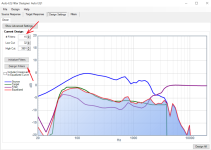
After the filter, an automatic equalizer module is installed, with which it is quite easy to make corrections to the frequency response of the speaker system.
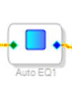
When you left-click on the equalizer module, a dialog box will appear in which you need to specify the location of the txt file with the measured frequency response of the speaker system.
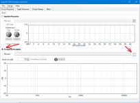
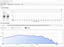
If the file was created correctly, the frequency response will appear in the window.
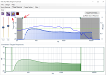
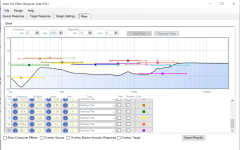
Then we go to the next tab and, using very flexible control tools, set the target frequency response, it can be suppressed using different methods and, in fact, you can set any arbitrary target frequency response in the frequency range we need.
After we have specified our target frequency response, we go to the next tab and specify the number of equalizer bands that will be used to obtain the target frequency response.
After clicking the Design Filters button, the program will automatically calculate the required values for the equalizer filters and show the result of the calculations.
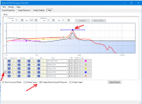
As can be seen from the calculation result in this example, 15 equalizer bands are redundant, you can get by with a smaller number of equalizer bands.
The convenience of this equalizer is that it is interactive, i.e. all the changes you make in the Filtrs window are not only visible on the graph, but they are automatically transferred to ADAU1452 and you hear the result. This greatly speeds up the fine-tuning of the equalizer parameters to suit your hearing.

When you left-click on the equalizer module, a dialog box will appear in which you need to specify the location of the txt file with the measured frequency response of the speaker system.

If the file was created correctly, the frequency response will appear in the window.

Then we go to the next tab and, using very flexible control tools, set the target frequency response, it can be suppressed using different methods and, in fact, you can set any arbitrary target frequency response in the frequency range we need.

After we have specified our target frequency response, we go to the next tab and specify the number of equalizer bands that will be used to obtain the target frequency response.

After clicking the Design Filters button, the program will automatically calculate the required values for the equalizer filters and show the result of the calculations.

As can be seen from the calculation result in this example, 15 equalizer bands are redundant, you can get by with a smaller number of equalizer bands.
The convenience of this equalizer is that it is interactive, i.e. all the changes you make in the Filtrs window are not only visible on the graph, but they are automatically transferred to ADAU1452 and you hear the result. This greatly speeds up the fine-tuning of the equalizer parameters to suit your hearing.

To obtain a text file with the results of measuring the frequency response of the speaker system, which can be added to the automatic equalizer in Sigma Studio, I use the export function in a very convenient and advanced free program for measuring speaker systems – REW.
After obtaining the frequency response of the speaker system, it must be exported to a txt file with the following settings.
Note that the required smoothing of the frequency response can be selected at will.

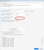
Next, you need to add two lines to the txt file so that Sigma Studio can correctly read the txt file with the frequency response of the speaker system.
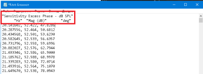
That's it, the file for Sigma Studio is ready and you can add it to the automatic equalizer.
After obtaining the frequency response of the speaker system, it must be exported to a txt file with the following settings.
Note that the required smoothing of the frequency response can be selected at will.


Next, you need to add two lines to the txt file so that Sigma Studio can correctly read the txt file with the frequency response of the speaker system.

That's it, the file for Sigma Studio is ready and you can add it to the automatic equalizer.
After the automatic equalizer, a crossover based on library FIR filters is installed in the project, which Sigma Studio calculates itself based on the parameters specified in the filter settings.
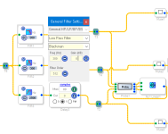
To control the adjustable crossover parameters, Probe is installed in the project. When you press the Probe button, a window will appear.
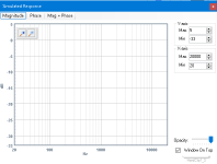
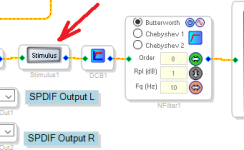
In order to display the graphs in this window, you must press the Stimul button.
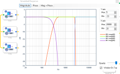
These graphs are active, i.e. when changing the crossover filter setting frequency, the window automatically displays the setting result.

In this case, there is no need to have a programmer connected to the ADAU1452; using this window, you can adjust the crossover in offline mode.
The NX1 adder is required to display the total frequency response of three bands on the graphs.

To control the adjustable crossover parameters, Probe is installed in the project. When you press the Probe button, a window will appear.

In order to display the graphs in this window, you must press the Stimul button.


These graphs are active, i.e. when changing the crossover filter setting frequency, the window automatically displays the setting result.

In this case, there is no need to have a programmer connected to the ADAU1452; using this window, you can adjust the crossover in offline mode.
The NX1 adder is required to display the total frequency response of three bands on the graphs.
- Home
- Amplifiers
- Class D
- 3 Way DSP Amp
