Hello!
Could you guys comment on the methods I followed for the 3-way projects I use to build?
Along the last 2 decades, I've built some loudspeakers for my self, family and friends, all 3-way port based with extended bass response down to 30Hz at least.
Always "old style" relatively big (>60 liters) with 8" or 10" woofer, 4" mid range and 1" dome tweeter.
I've used to electrically model the speakers on Pspice (eletronic circuit emulator) to get an idea of the real impedance.
I have a reasonable knowleadge of analog eletronic circuits.
I've always started with a theoretical LR aligment frequency cuts and slopes crossover and adjusted the crossover elements based on the circuit emulation result.
After building the final box, lots of intuitive adjustments always needed to be done playing with resistors/inductors/capacitors.
I understand that the speaker modeling I used to do only models the "piston" range of the speaker and not the rolloff range.
I basically compared the loudspeaker with a headphone and adjusted the elements by ear with reasonable results, not intended to have high-end units.
Last month, I've got a calibrated mic and decided to rebuild the 3-way loudspeaker crossover of my own pair of loudspeakers using REW to generate frequency response and impedance files for each speaker already seated in the loudspeaker baffle. I've loaded the 6 files in XSim.
Starting with a theoretical LR 12dB/oct circuit, I've got the usual result with lots of deeps and peaks and cancelations between speakers , which I used to more or less resolve inverting polarities here and there intuitivelly. I know in LR, we should invert the polarity of just the mid-range speaker.
This time, playing freely with the inductors/capacitors/resistors in XSim, I ended up with a good result (for my standards) both in the XSim simulation as well as in REW real measurements at the first try. Took a lot of iterations, since I fixed a certain range and got troubled in others.
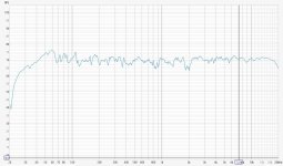
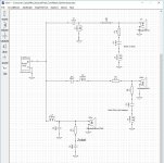
See the attached curves and schematic. These were indoor measurements at 25cm main axis, so disregard frequencies below 100Hz due to standing waves.
Just the tweeter frequency upper range didn't match much comparing simulation (XSim) and real measurement (REW).
I've made the adjustments (notch filter) for the real measurements, of course.
The only care I took was to observe the final minimum impedance (>4ohms) and the minimum frequency protection for the mid (>500Hz) and tweeter (>3kHz).
Looking at the schematic, it's completelly off from the theoretical LR aligment I've started with.
Mid-range ended up being just first order 6dB/oct with a notch to attenuate its breakup frequency peaks around 5 to 6kHz.
Woofer/tweeter 12dB/oct with a notch for the tweeter and a Zobel for the woofer.
Main question: what method you guys follow to adjust the crossover elements in XSim if the initial theoretical schematic doesn't get you a flat response at the first try?
Thank you!!
Could you guys comment on the methods I followed for the 3-way projects I use to build?
Along the last 2 decades, I've built some loudspeakers for my self, family and friends, all 3-way port based with extended bass response down to 30Hz at least.
Always "old style" relatively big (>60 liters) with 8" or 10" woofer, 4" mid range and 1" dome tweeter.
I've used to electrically model the speakers on Pspice (eletronic circuit emulator) to get an idea of the real impedance.
I have a reasonable knowleadge of analog eletronic circuits.
I've always started with a theoretical LR aligment frequency cuts and slopes crossover and adjusted the crossover elements based on the circuit emulation result.
After building the final box, lots of intuitive adjustments always needed to be done playing with resistors/inductors/capacitors.
I understand that the speaker modeling I used to do only models the "piston" range of the speaker and not the rolloff range.
I basically compared the loudspeaker with a headphone and adjusted the elements by ear with reasonable results, not intended to have high-end units.
Last month, I've got a calibrated mic and decided to rebuild the 3-way loudspeaker crossover of my own pair of loudspeakers using REW to generate frequency response and impedance files for each speaker already seated in the loudspeaker baffle. I've loaded the 6 files in XSim.
Starting with a theoretical LR 12dB/oct circuit, I've got the usual result with lots of deeps and peaks and cancelations between speakers , which I used to more or less resolve inverting polarities here and there intuitivelly. I know in LR, we should invert the polarity of just the mid-range speaker.
This time, playing freely with the inductors/capacitors/resistors in XSim, I ended up with a good result (for my standards) both in the XSim simulation as well as in REW real measurements at the first try. Took a lot of iterations, since I fixed a certain range and got troubled in others.
See the attached curves and schematic. These were indoor measurements at 25cm main axis, so disregard frequencies below 100Hz due to standing waves.
Just the tweeter frequency upper range didn't match much comparing simulation (XSim) and real measurement (REW).
I've made the adjustments (notch filter) for the real measurements, of course.
The only care I took was to observe the final minimum impedance (>4ohms) and the minimum frequency protection for the mid (>500Hz) and tweeter (>3kHz).
Looking at the schematic, it's completelly off from the theoretical LR aligment I've started with.
Mid-range ended up being just first order 6dB/oct with a notch to attenuate its breakup frequency peaks around 5 to 6kHz.
Woofer/tweeter 12dB/oct with a notch for the tweeter and a Zobel for the woofer.
Main question: what method you guys follow to adjust the crossover elements in XSim if the initial theoretical schematic doesn't get you a flat response at the first try?
Thank you!!
Attachments
 Moved to Multi-Way
Hi markbakk,
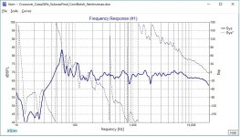
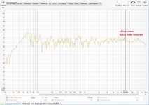
You are right! I've just measured 100cm away from the loudspeaker and the tweeter frequency region dropped by around 6dB as you mentioned.
See attached picture. So I may remove the notch or attenuate a bit less, since my listening place is around 2m (200cm).
For near field (25cm) there will be a small bump. And my baffle is all flat and 90 degrees for the lateral panels (simple rectangular box).
Thanks a lot for your comment!
Attachments
It's the other way around 😉 - https://www.diyaudio.com/community/...overs-without-measurement.189847/post-2587232the tweeter frequency region dropped by around 6dB as you mentioned.
The reason it measured lower is likely because you were further distant from it.
Thanks a lot for indicating that post. I've read all your initial post from 2011 and sure I'll go through the further discutions that took place along the 62 pages up until 2024. Lot of information I was looking for!!
🙂
🙂
Mid-range ended up being just first order 6dB/oct with a notch to attenuate its breakup frequency peaks around 5 to 6kHz.
Ahem, that's too low an order, and may cause you excessively low impedance curve. It's also going to cause too much interference with your tweeter especially when off-axis. Really suggest bumping this up to 2nd or 3rd order and adjusting the tweeter as needed.
Did you measure the driver offsets before starting? ?
I find that often when someone says they bought a “calibrated” mic, it means they got a USB mic since the USB mic copy usually pushes that.Did you measure the driver offsets before starting? ?
However we’d have to wait and see if the measurements were timed. There may not be the need to know the offsets.
However we’d have to wait and see if the measurements were timed. There may not be the need to know the offsets.
Sorry, by offset I meant physical distance. 🙂
Hello!
I'm using a dbx calibrated mic connected via XLR to an external pre-amp with phantom power (48V).
I've connected the pre-amp output to the PC sound card line input. So all analog.
When you you say "timed" of "offsets" what do you mean exactlty?
I'm still catching up with the details and terms of measurements (I'll go through all that 62-pages thread to learn more).
Mid and tweeter are aligned by the baffle surface so they are not aligned by their coils. I've just mounted them in the same plane (the front baffle).
One of the reasons I wanted to rebuild the crossover was to find a solution in such a way that I didn't had to reverse polarity of tweeter.
My original crossover, had woofer normal, mid reversed and tweeter reversed (so tweeter and mid in phase). If I left tweeter not reversed, there were strong cancellations around 3k to 5kHz +/-.
This new crossover has woofer normal, mid reversed and tweeter normal. No cancellations.
The physical misaligment between tweeter and mid I adjusted in the XSim - I set "Mod Delay" to "1.1 inch" in the mid-range speaker.
This 1.1 inch value I've got from a pre-test setup. I've connected the mid-range with no crossover and put a 3.3uF in the tweeter (woofer disconnected).
I've ran the simulation in XSim and made actual measurements with REW using same polarity and reversed polarity.
I've played with the Mod Delay until the results (peakes and notches) were similar (XSim and actual REW measurements).
After that, I've made all the complete simulations.
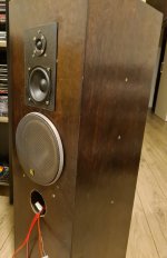
I've attached the front baffle picture of my loudspeaker.
Thank you!
I'm using a dbx calibrated mic connected via XLR to an external pre-amp with phantom power (48V).
I've connected the pre-amp output to the PC sound card line input. So all analog.
When you you say "timed" of "offsets" what do you mean exactlty?
I'm still catching up with the details and terms of measurements (I'll go through all that 62-pages thread to learn more).
Mid and tweeter are aligned by the baffle surface so they are not aligned by their coils. I've just mounted them in the same plane (the front baffle).
One of the reasons I wanted to rebuild the crossover was to find a solution in such a way that I didn't had to reverse polarity of tweeter.
My original crossover, had woofer normal, mid reversed and tweeter reversed (so tweeter and mid in phase). If I left tweeter not reversed, there were strong cancellations around 3k to 5kHz +/-.
This new crossover has woofer normal, mid reversed and tweeter normal. No cancellations.
The physical misaligment between tweeter and mid I adjusted in the XSim - I set "Mod Delay" to "1.1 inch" in the mid-range speaker.
This 1.1 inch value I've got from a pre-test setup. I've connected the mid-range with no crossover and put a 3.3uF in the tweeter (woofer disconnected).
I've ran the simulation in XSim and made actual measurements with REW using same polarity and reversed polarity.
I've played with the Mod Delay until the results (peakes and notches) were similar (XSim and actual REW measurements).
After that, I've made all the complete simulations.
I've attached the front baffle picture of my loudspeaker.
Thank you!
Attachments
Good. This runs alongside the microphone signal.. and by comparison to it, your separate measurements can be referred to the test signal. This means that the delay in the signal relates to the real physical delay between woofer and tweeter. It effects a change in phase.I've connected the pre-amp output to the PC sound card line input.
This change in phase is probably what you were looking for with your polarity task.
Good. Their surrounding surfaces will be smooth.Mid and tweeter are aligned by the baffle surface so they are not aligned by their coils. I've just mounted them in the same plane (the front baffle).
You should set the mod delay in Xsim to 0. It's only there for people who use flat response plots without measured delay.The physical misaligment between tweeter and mid I adjusted in the XSim - I set "Mod Delay"
Hi!
You mentioned to set mod delay to 0 in XSim. But how do I model in XSim the physical misaligment I have between the tweeter and mid-range coils?
When you mention delay, do you mean the digital delay which a USB mic causes?
If I set the mic let's 50cm away from the loudspeaker and take all the 3 speakers measurements without moving anything (not a single milimeter), would the misaligment effect already be in the measurements? Is that what you mean?
Thank you!!
I don't think TS meant a dual channel measurement setup here. @TS: make sure you have a dual channel sound card and connect left output with left line input. That will be your timing reference signal. Use the right output to the amp and the right input for the mic preamp. Set REW up accordingly and you're all set to measure dual channel with absolute timing reference. Then repeat the measurements.Good. This runs alongside the microphone signal.. and by comparison to it, your separate measurements can be referred to the test signal.
Additionally, try to get acquainted with using gated measurements.
Possibly.I don't think TS meant a dual channel measurement setup here.
Hi markbakk,
Interesting. So, when you guys mean "timed" measurements, you mean that REW must have an electrical reference on which the acoustic measurement can be refered to. Great! I'll do my homework here by studying this matter and see what I did and redo if not correct.
Thanks a lot!
Interesting. So, when you guys mean "timed" measurements, you mean that REW must have an electrical reference on which the acoustic measurement can be refered to. Great! I'll do my homework here by studying this matter and see what I did and redo if not correct.
Thanks a lot!
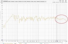
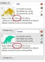
Hi! I've just confirgured REW with timing reference and it worked! See picture.
It indicated that mid-range is 25mm farther than the tweeter, which makes sense and was about my estimative of 1.1inch (27,5mm) and matches the dimensions of my speakers. So I think I'm good to go now. I'll redo all measurements, load in XSim (remove the mod delay) and see what I get.
I understand that I have to keep the mic and loudspeaker exatcly in the same position for measuring all 3 speakers, right?
Any milimetric movement and I will loose the measurements.
Thanks a lot!!
Attachments
- Home
- Loudspeakers
- Multi-Way
- 3-Way Crossover Design - Method for adjusting XSim