The input impedance of your last circuit is (roughly) 10K || 2K || 470 || (Q1.hfe * R6).
So it's a bit low for an amplifier.
As far as feedback goes, your output is 180deg phase WRT input, so if you feed back from Q2 emitter to Q1 base, you will be fine.
You need to have a resistor in series with C1 (on the amp side), and play with that value and the feedback impedance value to adjust the feedback ratio.
Of course, you will have to bump the VAS gain, playing with R5/R6 values.
Also, is you feed from Q1 emitter to Q3 base, you should be able to turn Q3 into an active current generator, possibly lowering the class quiescent current.
Sorry. Not in here very often.-)
# 33, # 35: http://www.diyaudio.com/forums/power-supplies/289669-supply-amps-help-pcb.html
# 33, # 35: http://www.diyaudio.com/forums/power-supplies/289669-supply-amps-help-pcb.html
3-Transistor HeadAmp with feedback
Hi jstott
I know its been a while, but I only just read this thread recently, but better late than never!
The design is refreshingly simple, but with simplicity comes certain problems. In this case the (lack of) real PSSR.
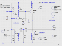
This problem could be solved with proper negativ feedback. The challenge is do it with just 3 trans, but I believe I have come up with two solutions (see attached schematics and tlspice files).
In the first attempt, I basically switched Q2 to a PNP and added NFB from the output to emitter of Q1 thereby forming a Complementary Feedback Pair (CFP). A note: I've tried to separate dc-feedback and ac-feedback in order to make the gain independed of the dc operating point. The performance of this circuit is (with respect to distortion) is quit depended of the load. I have a pair of Senheiser Momentum with an impedance on 18 ohms, they do require a lot current, hence the rather large output capacitor. Further I added a capacitor at the input bias scheme, in order to (further) increase the PSRR.
In my second attempt, I sacrified the constant current, and went for more available gain. Basically this means I had to double the standing current, now more than 300mA. Also the dc voltage on the output should be closer
to 6V in order to have more negativ drive.
I havent physically build any of them (I intend to!), but they both sims quite allright (2nd and 3rd order harmonics below 0.1% before clipping) and PSRR in the order of 40dB and better.
Cheers
Lars L.P.
Hi jstott
I know its been a while, but I only just read this thread recently, but better late than never!
The design is refreshingly simple, but with simplicity comes certain problems. In this case the (lack of) real PSSR.
This problem could be solved with proper negativ feedback. The challenge is do it with just 3 trans, but I believe I have come up with two solutions (see attached schematics and tlspice files).
In the first attempt, I basically switched Q2 to a PNP and added NFB from the output to emitter of Q1 thereby forming a Complementary Feedback Pair (CFP). A note: I've tried to separate dc-feedback and ac-feedback in order to make the gain independed of the dc operating point. The performance of this circuit is (with respect to distortion) is quit depended of the load. I have a pair of Senheiser Momentum with an impedance on 18 ohms, they do require a lot current, hence the rather large output capacitor. Further I added a capacitor at the input bias scheme, in order to (further) increase the PSRR.
In my second attempt, I sacrified the constant current, and went for more available gain. Basically this means I had to double the standing current, now more than 300mA. Also the dc voltage on the output should be closer
to 6V in order to have more negativ drive.
I havent physically build any of them (I intend to!), but they both sims quite allright (2nd and 3rd order harmonics below 0.1% before clipping) and PSRR in the order of 40dB and better.
Cheers
Lars L.P.
Attachments

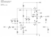
Here's another take 🙂
Of course, there are variable resistors for biasing (R2 and R7).
Of course, there are variable resistors for biasing (R2 and R7).
Attachments
Last edited:
Here's another take 🙂
Of course, there are variable resistors for biasing (R2 and R7).
As it is, the above is of course likely to be subject to thermal runaway, unless, instead of R7, a proper compensation is implemented (which requires another BJT or a couple of diodes).
Alternatively, instead of Q2 and Q3 being BJTs, something like a complementary mosfet as TN2640 / TP2640 are used.
These are thermally stable, fast, have low Vgs-on and have relatively small input capacitance.
A 3 transistor headamp with good performance. http://www.diyaudio.com/forums/headphone-systems/263801-classic-50mw.html
As it is, the above is of course likely to be subject to thermal runaway, unless, instead of R7, a proper compensation is implemented (which requires another BJT or a couple of diodes).
Alternatively, instead of Q2 and Q3 being BJTs, something like a complementary mosfet as TN2640 / TP2640 are used.
These are thermally stable, fast, have low Vgs-on and have relatively small input capacitance.

Nice design. I have all these parts and might P2P t for fun.
Can you really have thermal runaway with only 9v of supply voltage? On F5HA, we are using +/-15v rails and IRF610/9610 (or 2SK2013/2sJ313) in class A at 200mA and do not worry about runaway.
Btw, with only an extra transistor you have the F5HA (not power stingy) - one of the best sounding head amps around.
Or 4 transistors also gets you another top performer:
http://www.diyaudio.com/forums/headphone-systems/95841-mosfet-follower-headphone-amplifier.html

Last edited:
Thermal runaway, in theory yes.
Some current is flowing across some voltage. This mean power dissipated by the BJT.
Power dissipated means and increase of temperature, which lowers the Vbe at the same current (or, allows more current with the same Vbe), which highers the current across the BJT, ...
Using the TN2640 / TP2640 and a slightly modified circuit (4.7 Ohm -> ~1.2 Ohm source output resistors, add 330 Ohm gate resistors, and maybe a feedback shortcut capacitor of 100pf or so across R4), should make that stable.
But that turns the 3-bjt amp, to a 1-bjt & 2-fet one 😀
If PSU can supply say 1 amp at 9v then max power dissipation is 9w in the worst case. Most TO220's can dissipate 9w safely and easily if heatsinked.
Yes, but you end up with a PSU on its knees if you let the BJTs draw 1A at idle.
You can try. Increasing the output emitter resistor values has the effect of stabilizing thermal runaway, but also make feedback phase to fall behind on capacitive loads.
You can try. Increasing the output emitter resistor values has the effect of stabilizing thermal runaway, but also make feedback phase to fall behind on capacitive loads.
PSRR is simple to fix - use a voltage regulator. The problem the design has is noise in the input stage. I never found a good solution to that one.
I do havesome other designs I want to try, but I want to build them and have a listen before I post anything. With my work schedule, that may be a while.
-JS
I do havesome other designs I want to try, but I want to build them and have a listen before I post anything. With my work schedule, that may be a while.
-JS
You cannot fix nonexistant PSRR by just putting in a regulator. It generally takes more than that. Regulators are notoriously noisy after all. A standard 78M series part might have 5 µV per V of output voltage, 0-10 kHz - and that's not as bad as it gets by far. I reckon that's your problem.
With "princess on a pea" circuits like that, you end up putting a lot of effort into the power supply to make them work well - a cap multiplier here, some passive RC cleanup there, maybe a superregulator even. So it's not like you're saving much in terms of complexity in the end.
The other extreme - not caring for power supply noise at all but employing circuitry with extremely high PSRR - also has its problems. It takes very little e.g. in terms of common ground return impedance to spoil said extremely high PSRR, so it's quite demanding with little margin for error.
Generally you best end up somewhere in the middle, with decently low noise power supplies and decently high PSRR on your circuitry.
This amplifier uses only 2 transistors, and has about 24dB PSRR within its passband; not much, sure, but better than non-existent:
http://www.diyaudio.com/forums/solid-state/228913-two-transistor-push-pull-ab-amplifier.html
http://www.diyaudio.com/forums/solid-state/228913-two-transistor-push-pull-ab-amplifier.html
- Status
- Not open for further replies.
- Home
- Amplifiers
- Headphone Systems
- 3-Transistor Headphone Amplifier