So, I was playing around trying to make the simplest amplifier I could. I ended up aiming for a low-power headphone amplifier, just to keep it simple, designed to drive ordinary cheap low-impedance headphones (iPod ear buds and the like, 20-30 ohm load at DC). The design works far better than it has any right to, so I though I would share it.
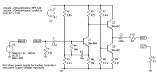
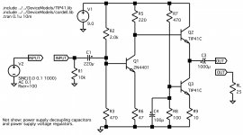
The amplifier design is fairly conventional (schematic attached). It's a single-ended class-A amplifier with no feedback, all solid-state [no opamps]. A small wall-wart and a voltage regulator are all it needs for power. TO-220 output transistors were happy without heat sinks, but I didn't want to push it into full clipping so I think I'll add some small ones when I do a permanent build. Because of its low gain and output design, stability and short-circuit protection are excellent.
Frequency response is flat to out beyond 1 MHz. Spice says distortion is is in the 0.5% range and, as expected, increases as the volume increases. I'm no golden ear, but I couldn't hear any audible distortion. Using the headphone jack on my laptop as a source, the tops and bottoms were definitely stronger with the amplifier than driving the headphones directly (but that could just mean the computer is happier driving the higher input impedance of the amplifier).
Nothing in the part selection is critical - I just used what I had on hand. If you want to substitute transistors, feel free. The output transistors, Q2 and Q3, need to dissipate as much as 0.5W [worst-case] and quiescent current is 70-100 mA, so I don't recommend using small-signal TO-92 transistors there, but any tabbed power transistors should be fine. I've also tried using a MOSFET instead of a BJT for Q2 and, other than needing a higher input biasing, it worked just fine. Q1 can be any small-signal transistor but the linearity is better with higher-current models like 2N2222/2N4401 rather than the smaller 2N3904's. R2 and R3 bias the input stage, R7 and R8 bias the output current source - if you swap transistors you may have to tweak these biasings a little. R10 is there to decrease the output power and swamp any possible parasitic cable reactance (hence no output Zobels). If you want to leave it out, the amplifier should still work just fine.
My only complaint is that there's more hiss than I expected. It's there even with grounded inputs, so it's definitely coming from the amplifier. Spice says this should be a nice low-noise design (sub-uV RMS noise), so that one's got me scratching my head. For trials I was using a bench power supply and some 10u decoupling caps, so it's not on-board regulator noise.
-Jonathan
Attachments
Interesting and elegant design, have you considered paralleling R8 with a large electrolytic or replacing it with a red led or green led - match Vf to what you need to bias Q3 to your desired Q point. This should help with the hiss as the johnson and excess noise generated by R7/R8 is currently amplified by Q3.
Potentially C2 is a bit small, have you calculated the -3dB point of the bootstrap?
Potentially C2 is a bit small, have you calculated the -3dB point of the bootstrap?
Interesting and elegant design, have you considered paralleling R8 with a large electrolytic or replacing it with a red led or green led - match Vf to what you need to bias Q3 to your desired Q point.
I tried the LED (in simulation). Diode biasing works with the BJT, but with a MOSFET I just didn't have enough control of the bias level (the extra 3.5V drop doesn't leave much headroom on the output).
This should help with the hiss as the johnson and excess noise generated by R7/R8 is currently amplified by Q3.
Good point. Simulation said an extra cap wouldn't help so I left it off, but of course simulation also said there wouldn't be any hiss. I'll try it for real this weekend when I have some more time.
Potentially C2 is a bit small, have you calculated the -3dB point of the bootstrap?
The -3dB point I get is 12 Hz. I'm content with that, but it's easy enough to swap it out with a 22uF capacitor.
Thanks for the feedback,
Jonathan
I can see some potential for improvement there.
1. The output is referred almost directly to the +9V rail. PSRR is near zero. Might explain why the circuit is noisy. Try using +9V as output ground (while reversing C3).
2. The current through R7/R8 would seem to be too small for Q3 to serve as a good current source - try reducing them by about a factor of 10. R9 also strikes me as a bit small. Also consider adding a diode in series with R8 (1N4001-ish?), thermally coupled to Q3 (hint: transistor legs have pretty good thermal conductivity).
3. Consider splitting and bootstrapping R5 from the output and adding current feedback from the output to R6. Reverse (1.) then.
4. Also consider going for a PNP Q1 (turning associated circuitry upside down) and -9V supply, referencing everything to +Vunreg (which becomes your new ground). That would give you a clean ground for both stages.
5. TIP41C (6 A) are rather big for an application like this, try TIP31C (3 A) or BD139 (1-1.5 A) instead.
Schematic version 2.0
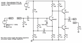
The core design is the same, but I've updated the schematic to include some of the suggestions by kevinkr and sgrossklass.
As I said in the original post, component selection is based on what I had in the drawer; the output transistors are not optimal so feel free to substitute. Also, as sgrossklass pointed out, the amplifier has basically no PS rejection. A voltage regulator (LM317, LM7809, or similar) on the supply rails is pretty much mandatory to hold down the supply hum. Personally, I plan on using a 12V wall-wart and regulating down to 9V using a separate regulator for each channel when I get around to boxing the whole thing up.
-Jonathan
The core design is the same, but I've updated the schematic to include some of the suggestions by kevinkr and sgrossklass.
- The bias currents are now higher, which fixed the background hiss. Replacing R8 with an LED is another variation on the same theme.
- The input stage is limited in how much current it can source without distorting, so I increased the output emitter resistor (R9) to keep the quiescent current at about the same level as before.
- Smaller resistors also require bigger capacitors to preserve the bass.
- The output capacitor may be a bit marginal at 470 uF, depending on your headphone impedance. 1000 uF should be happy even with 20-ohm headphones.
- I decide the volume-limiting resistor, R10, wasn't worth the bother so I left it out.
- Finally, I noticed that if you over-drive the input, the bootstrap causes the input transistor to back-bias. If taken to extremes (ca 5-10V input), it could even destroy Q1 by exceeding its maximum base-emitter reverse voltage. To protect the transistor, I've added D1 which limits the worst-case base-emitter voltages to about -0.8V. During normal operation, the diode is reverse biased and it doesn't pass current.
As I said in the original post, component selection is based on what I had in the drawer; the output transistors are not optimal so feel free to substitute. Also, as sgrossklass pointed out, the amplifier has basically no PS rejection. A voltage regulator (LM317, LM7809, or similar) on the supply rails is pretty much mandatory to hold down the supply hum. Personally, I plan on using a 12V wall-wart and regulating down to 9V using a separate regulator for each channel when I get around to boxing the whole thing up.
-Jonathan
Attachments
The bias voltage (approximately equal to base voltage) is more positive than the emitter, so I think it's drawn right. honestly, I just used a voltmeter when I built it.Isn't C2 reverse biased ?
The AC voltage across the cap will be extremely small in normal operation, and the cap will always be properly polarized. Once the driver stage clips behavior will get nasty, but since this is a headphone amplifier it is unlikely to be tolerated for any length of time.
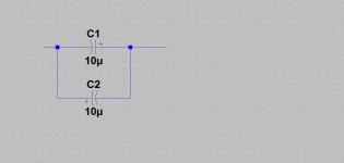
The connection shown is not correct for a bipolar capacitor in my experience - if any significant level of DC is present one of the capacitors will become reverse biased which may lead at best to significant leakage and at worse a shorted cap. (Steering diodes would normally be used with the shown connection and this is not suitable for use in audio applications, but is not uncommon in DC blocking applications on AC mains)
The connection shown is not correct for a bipolar capacitor in my experience - if any significant level of DC is present one of the capacitors will become reverse biased which may lead at best to significant leakage and at worse a shorted cap. (Steering diodes would normally be used with the shown connection and this is not suitable for use in audio applications, but is not uncommon in DC blocking applications on AC mains)
Maybe consider back to back 10uF electros there to form a non-polar. Then you are covered no matter how large the input swing.
Pretty sure that's not how to form a non-polar... and the picture is showing parallel anyway
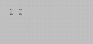
Back to back is correct tho.
Lol! That is what I get for posting late when I'm tired. 😛
The caps do have to be in series. A reversed biased electro is rather like a diode and will conduct.
And definitely true about the voltage across a coupling cap. It will be small through the audio band.
Off to find coffee... 🙂
The caps do have to be in series. A reversed biased electro is rather like a diode and will conduct.
And definitely true about the voltage across a coupling cap. It will be small through the audio band.
Off to find coffee... 🙂
Attachments
Hi everyone,
i have build the second version of this headphone amp http://www.diyaudio.com/forums/head...ansistor-headphone-amplifier.html#post4698732, just for fun and because it is so simple, but it really sounds amazing. Very detailed, good bass, more than decent drive capability etc... So, it ended up in a small box, and is currenty being used as my main headphone amp.
Only problem is the hf noise, mainly on my sensitive earbuds, my philips 32ohm closed headphones don't produce anywhere near that noise level. Just the slightest, faintest suspicion of background noise. I should note that there is no ps hum or buzz, the regulators are doing their job properly down there....
In an attempt to reduce the hf noise (a distracting shhhhh kind of noise), i tried various things. An input rc filter at about 50Khz and a 1000μF electrolytic just across each amp module (there is about 15cm of twisted pair after each regulator), seemed to do wonders, especially the electrolytic decoupling caps. Of course, there is "plenty" of decoupling capacitance, right on the pins of the regulators (470μF at the inputs and 270μF solid state caps at the outputs). I should also mention that everything is point to point, no pcbs for this experimental build...
Any ideas on how to improve this little beast even further??
Hi everyone,
i have build the second version of this headphone amp http://www.diyaudio.com/forums/head...ansistor-headphone-amplifier.html#post4698732, just for fun and because it is so simple, but it really sounds amazing. Very detailed, good bass, more than decent drive capability etc... So, it ended up in a small box, and is currenty being used as my main headphone amp.
Only problem is the hf noise, mainly on my sensitive earbuds, my philips 32ohm closed headphones don't produce anywhere near that noise level. Just the slightest, faintest suspicion of background noise. I should note that there is no ps hum or buzz, the regulators are doing their job properly down there....
In an attempt to reduce the hf noise (a distracting shhhhh kind of noise), i tried various things. An input rc filter at about 50Khz and a 1000μF electrolytic just across each amp module (there is about 15cm of twisted pair after each regulator), seemed to do wonders, especially the electrolytic decoupling caps. Of course, there is "plenty" of decoupling capacitance, right on the pins of the regulators (470μF at the inputs and 270μF solid state caps at the outputs). I should also mention that everything is point to point, no pcbs for this experimental build...
Any ideas on how to improve this little beast even further??
Have you checked for parasitic oscillation? There is no base stopper resistor on the emitter follower. Perhaps this may help.
Hmm...
Thanks, didn't think of that. Unfortunately, i don't have a scope.
I'll try maybe some ferrite bead or small choke at the base of Q2 to see if that helps.
Thanks, didn't think of that. Unfortunately, i don't have a scope.
I'll try maybe some ferrite bead or small choke at the base of Q2 to see if that helps.
Perhaps a quieter way to bias Q3 is the next area to look at. (The noise generated in the resistors in the bias network is amplified by Q3 and while not a lot given the sensitivity of your headphones might be enough to be significant.) Try shunting R8 with a 22uF electrolytic temporarily and see if that helps the hiss.
Thanks. I'll try the R8 cap when i reopen the box. I will also try to bring the regulators as close as possible to the amps.
Improving, much more homogenity by parts:
- replace all single-caps by a pack of 4 - 5, put at one circuit
- higher the capacitance at the amps much more
- do not use different caps
- do not use channel-separated psu
- try to remove or higher R1
- same Q for all
- regulated bias Q3, shunt R8; as mentioned
- do not use lace or big diameters
- ...-?
Dear cumbb,
i'm sorry, maybe it's my bad english, but i did not understand half of your proposals (maybe more)! Can you elaborate on what you are proposing?
And what exactly do you mean by saying "do not use channel-separated psu"? If you mean single transformer and single bridge rectifier/filter caps, thats how my setup is working. If you mean single regulator for both channels, how is that going to help?
As experiment I would try to feed from Q1 emitter to Q3 base with a proper resistor (turn Q3 into active current source), and add current feedback from Q2 base to Q1 emitter.
With feedback in place R5/R6 will have to be recomputed of course.
With feedback in place R5/R6 will have to be recomputed of course.
Version 3-beta
Hi All,
Just to maybe move this along, there's also a third generation circuit. I've simulated it but I haven't had time to build it: it may help, it may not. But, since the thread has sprung back to life I thought I would share it with everyone. Main change: I've decided that the input capacitor, C2, was a stupid idea so I took it out. This improves the THD (now simulating at 0.15% at near full volume).
I don't think the changes will improve the noise though, and I may have made it worse (won't know for sure until I build it). As others have already pointed out, the source of the noise seems to be the base and emitter resistors of Q1. The current gain stage (Q2,Q3) is a minor contributor to the noise, but I added C4 anyway to reduce its noise bandwidth just in case. The value of C4 is non-critical, but bigger is probably better.
The constraint I run into is keeping the input properly loaded without using absurd amounts of idle current through Q1. R6 should be in the 20-50 ohm range to keep the current down. That gives a conservative 2k-5k of input impedance to Q1. R2||R3 has to be smaller than that, say 200-500 ohms, but if its too small C1 has to become very large or else you will lose bass response. R2||R3 is also the amplifier input impedance, so if it's too small your source may have trouble driving the amplifier.
A few people have suggested adding current feedback and maybe I'm just being dense today, but I don't see how to implement it nor why it will help. There's only 10 dB of voltage gain, so there's isn't much to give back as feedback. Moreover, after Q1 everything moves in-phase, so everything I've tried in Spice either gives positive feedback (not helpful) or makes no difference in the output (also not helpful).
Adding more transistors (active load for Q1, etc) as others suggest would certainly help, but that sort of defeats the idea of building a simple 3-transistor amplifier. With four transistors, for example, one could build a scaled-down JLH.
Final note to anyone building this: I suggest replacing R2/R3 and R7/R8 with variable resistors until you're happy with the voltage levels. With no feedback and low gain, the amp is very stable, so put it on a proto-board to play around with it until you're happy. R2/R3 should be set to maximize Q1's dynamic range. R7/R8 sets the current through Q3. Keep turning it down until you start to clip (run out of current) at max volume. The resistor values on the schematic are good starting points, but there are no magic values here.
Attachments
- Status
- Not open for further replies.
- Home
- Amplifiers
- Headphone Systems
- 3-Transistor Headphone Amplifier