Hi
I hope you don't mind me contacting you regarding this post which is around a year old now?
I built my own turntable last year, a good description and photos etc were posted on vinyl engine under the same user name if you are also on there.
However I am interested in improving the motor drive. I require a motor that will drive a 40mm diameter pulley at 250 rpm, single speed. This pulley drives the 300mm dia rim of my large mdf platter, so it needs to have a bit of torque to get it going. At the moment I'm driving a stepper motor as per a synchronous motor with a 19v AC supply and phasing capacitor. But it's a bit noisy and there's some of its vibration getting picked up.
It sound like your BLDC motor would be ideal? But I'm not sure how to obtain a motor such as you have and what is involved in the setup - would you be kind enough to provide me links to the motor and control boards you used if available? I am in the UK.
Also you mention some programming - do you mind giving a few more details how this is done and what setup is required?
Many thanks for any pointers you can provide.
- realjuliano
Yes, if you don't lower the drive voltage!Thanks for the reply. I've struggled to find any clear explanation of this phenomenon.
Question about trying to maintain a 90° lead between field and rotor: Won't this accelerate the rotor in the absence of a heavy load?
But that's the idea, to (once the motor is up to speed and in sync) use the phase angle as the error part of the feedback loop, and the motor voltage as the correction (with the addition of whatever PID stuff it takes to give stability). If the angle goes above 90 degrees, the motor voltage is increased to bring it back to 90. If it goes below, the motor voltage is decreased so so that friction and drag bring it up to 90.
If your angle sense is instant (or fast enough), this gives instant control of the motor - increase in voltage drive causes increase in torque, which causes the angle to reduce.
If you have full voltage to the motor with the rotor going full speed, the rotor is (theoretically) at 0 degrees, or with the usual friction, just a couple of degrees behind the field. If there's any increase in drag, this angle WILL increase because you're already giving full voltage to the motor! With the rotor delayed behind the field (and the motor current reduced appropriately), you've got headroom to increase torque when an increase in friction causes the rotor to lag behind the set angle.
You're surely right in that this may be overkill, but as an engineer I think of how things can go wrong and how to fix them. As for the belt drive, an increase in friction will surely cause (or add to) belt creep, but then that would be outside the feedback loop. To fix this would require direct detection of the platter speed as input to wrap a feedback loop around the belt.I've had a number of discussions with other engineers regarding stylus drag and torque, but not with anyone who has a firm grasp of the physics. Static drag (the difference between needle up and needle on the record) is measurable but extremely small. Since it doesn't change (or only extremely slowly from outer grooves to inner grooves), the phase angle of the rotor/field should remain constant as well. I haven't been able to measure dynamic drag (loud/soft or bass/treble passages) even with a tachometer with 3 decimal places of resolution. In theory, it must exist, but it also must be infinitesimally small, and by its very nature, momentary and short lived. I would think the inertia of the platter would make this even more difficult to detect.
To add to the difficulties, with a direct drive, this would show up as a infinitesimally small change in the rotor/field phase angle, but with a belt drive, would it not manifest itself as additional belt creep as well, possibly never reaching the motor?
I still think the best way to drive a belt drive motor is maintain constant current and frequency and let the rotor find its own phase angle with the field. The largest deviation will occur at platter start up. Once the platter is up to speed and the stylus is on the record, the torque load should be nearly constant. Sudden changes due to dynamic drag should be ameliorated by platter inertia and longer term dynamic drag would produce a new constant load that shouldn't create any audible time smear.
Thoughts?
And when we get to a "perfect turntable" we get to the point of worrying about whether the cutting lathe had varying speed problems - the drag from the cutting stylus is surely much greater than for a playback stylus.
It sound like your BLDC motor would be ideal? But I'm not sure how to obtain a motor such as you have and what is involved in the setup - would you be kind enough to provide me links to the motor and control boards you used if available? I am in the UK.
Also you mention some programming - do you mind giving a few more details how this is done and what setup is required?
Many thanks for any pointers you can provide.
- realjuliano
The motors I am using are available from Anahiem Automation. The BLWS231S-24V-2000 is a 4 pole motor so it would require a drive frequency of 8.333Hz for 250 RPM. The BLWR172S-24V-2000 is an 8 pole motor which would require a 16.667Hz drive signal for 250 RPM. The BLWS series uses a 0.25" shaft, the BLWR series has a 4mm shaft. If you turned a pulley for 500 RPM, double the drive frequency for each motor.
The controller I'm using is custom built for the motor I chose. You could use the SG4 sinewave generator to generate the sinewaves, but it would require an update to the firmware in order to go that low in frequency. You would also need 3 channels of amplification to drive the motor windings. Low cost amps are available on e-Bay, but they need to be single ended output (non-bridge tied load types).
I'm looking at putting together a 3 channel amp based on LM3886 chip amps that would be suitable for these motors. I can update the firmware in the SG4 to reduce the lower frequency limit. Together, the two projects should make using these motors feasible.
If your angle sense is instant (or fast enough), this gives instant control of the motor - increase in voltage drive causes increase in torque, which causes the angle to reduce.
This is where I see a problem with doing this with belt drive. There will be a sizable delay in not only detecting the change in load, (due to platter inertia, belt stretch & creep) but also in correcting the drive signal for the same reasons, plus the additional delay in loop BW and PWM output LPF delay. I think this will be much more practical in a direct drive where platter mass is much lower and the drive system is not elastic.
If you have full voltage to the motor with the rotor going full speed, the rotor is (theoretically) at 0 degrees, or with the usual friction, just a couple of degrees behind the field. If there's any increase in drag, this angle WILL increase because you're already giving full voltage to the motor! With the rotor delayed behind the field (and the motor current reduced appropriately), you've got headroom to increase torque when an increase in friction causes the rotor to lag behind the set angle.
In practice, I reduce the voltage to the motor once the platter is up to speed as maximum torque is no longer needed. The rotor/field angle will slip with a change in load, but I wonder if this could even be measured with dynamic drag? If it could, it would be possible to increase the voltage accordingly. Also, I wonder if running at an angle less than 90° would be better. 90° produces maximum torque, but if the angle slips above that because of increased load, torque output diminishes and you risk stalling the motor.
You're surely right in that this may be overkill, but as an engineer I think of how things can go wrong and how to fix them. As for the belt drive, an increase in friction will surely cause (or add to) belt creep, but then that would be outside the feedback loop. To fix this would require direct detection of the platter speed as input to wrap a feedback loop around the belt.
This is also a big problem. Using a test record with a 3150Hz tone, even the slightest touch to the platter will cause a drop in tone pitch, due almost entirely to belt creep. Pressing my thumb on the motor pulley produces no perceptible change in pitch, up to the point where the motor stalls. No matter how carefully you design the motor control, belt creep will dominate the loss of speed with load.
And when we get to a "perfect turntable" we get to the point of worrying about whether the cutting lathe had varying speed problems - the drag from the cutting stylus is surely much greater than for a playback stylus.
Agreed.
This is also a big problem. Using a test record with a 3150Hz tone, even the slightest touch to the platter will cause a drop in tone pitch, due almost entirely to belt creep. Pressing my thumb on the motor pulley produces no perceptible change in pitch, up to the point where the motor stalls. No matter how carefully you design the motor control, belt creep will dominate the loss of speed with load.
I appreciate that in theory this will always be the case, but would it help significantly if a less flexible belt, e.g. Mylar tape is used?
I was thinking of using a composite of Mylar tape and silk ribbon; with the tension applied by resiliently mounting the motor housing
I was also considering using a crowned rubber surface on the motor pulley to provide as much grip as possible.
Last edited:
I appreciate that in theory this will always be the case, but would it help significantly if a less flexible belt, e.g. Mylar tape is used?
I was thinking of using a composite of Mylar tape and silk ribbon; with the tension applied by resiliently mounting the motor housing
I was also considering using a crowned rubber surface on the motor pulley to provide as much grip as possible.
Belt creep is caused by uneven stretching of the belt between the side entering the drive pulley and the side leaving the drive pulley. The lower the elasticity, the less belt creep exists. However, the more rigid the belt, the more motor vibrations that can be conducted to the platter.
Another problem with rigid belt materials is maintaining proper tension. Sometimes and idler pulley is used to keep constant tension on the belt. Using a rubber pulley will help with belt slip, but not belt creep. A rubber pulley will also be more difficult to machine concentric vs metal or Delrin.
I'm looking at putting together a 3 channel amp based on LM3886 chip amps that would be suitable for these motors. I can update the firmware in the SG4 to reduce the lower frequency limit. Together, the two projects should make using these motors feasible.
See, that is the kind of thing making one's day. 🙂
BLDC motors and SG4
Thanks very much for the above info, I had already seen your 4 phase sine wave generator.. it looks great and I'd like to make one anyone to try to improve the drive of my current synchronous motors. I presume for a normal ac motor you just need a 2 channel amp, but I'd be happy to wait for the one you are planning to build. Or if anyone wants to point me in the direction of a suitable eBay amp for now.
By the way has anyone in the UK got a spare board for the SG4 I could buy from them?
I guess the above should be on the sine wave generator post.. will try to include it there as well.
Regarding the motor itself, I read somewhere that the motors stripped from old hard drives were BLDC multi phase types - have you any experience as to if they would be suitable for the task?
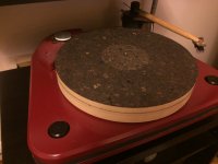
Sorry for my probable ignorance but just a comment on the belt issues mentioned above if it's any help to anyone. I'm driving a heavyish 36mm thick 300mm MDF platter from the rim with a 40mm pulley. The best material I've found for the belt is 'braid' type fishing line. It doesn't stretch and it's fine enough that the knot sits in such a way as to not create a 'lump'. For a while I felt that the speed was just a hair slow to my ear. I corrected this with a single wrap of PTFE around the smaller pulley - now it seems perfect to me although I have to renew the PTFE occasionally. Hopefully there's a picture below to show what I mean.
The motors I am using are available from Anahiem Automation. The BLWS231S-24V-2000 is a 4 pole motor so it would require a drive frequency of 8.333Hz for 250 RPM. The BLWR172S-24V-2000 is an 8 pole motor which would require a 16.667Hz drive signal for 250 RPM. The BLWS series uses a 0.25" shaft, the BLWR series has a 4mm shaft. If you turned a pulley for 500 RPM, double the drive frequency for each motor.
The controller I'm using is custom built for the motor I chose. You could use the SG4 sinewave generator to generate the sinewaves, but it would require an update to the firmware in order to go that low in frequency. You would also need 3 channels of amplification to drive the motor windings. Low cost amps are available on e-Bay, but they need to be single ended output (non-bridge tied load types).
I'm looking at putting together a 3 channel amp based on LM3886 chip amps that would be suitable for these motors. I can update the firmware in the SG4 to reduce the lower frequency limit. Together, the two projects should make using these motors feasible.
Thanks very much for the above info, I had already seen your 4 phase sine wave generator.. it looks great and I'd like to make one anyone to try to improve the drive of my current synchronous motors. I presume for a normal ac motor you just need a 2 channel amp, but I'd be happy to wait for the one you are planning to build. Or if anyone wants to point me in the direction of a suitable eBay amp for now.
By the way has anyone in the UK got a spare board for the SG4 I could buy from them?
I guess the above should be on the sine wave generator post.. will try to include it there as well.
Regarding the motor itself, I read somewhere that the motors stripped from old hard drives were BLDC multi phase types - have you any experience as to if they would be suitable for the task?
Sorry for my probable ignorance but just a comment on the belt issues mentioned above if it's any help to anyone. I'm driving a heavyish 36mm thick 300mm MDF platter from the rim with a 40mm pulley. The best material I've found for the belt is 'braid' type fishing line. It doesn't stretch and it's fine enough that the knot sits in such a way as to not create a 'lump'. For a while I felt that the speed was just a hair slow to my ear. I corrected this with a single wrap of PTFE around the smaller pulley - now it seems perfect to me although I have to renew the PTFE occasionally. Hopefully there's a picture below to show what I mean.
Attachments
BLDC from HDD
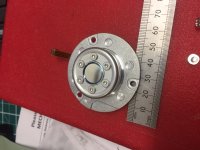
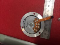
I've just extracted a BLDC motor from an old hard drive - pics attached
it's a beautiful little motor and really easy to attach a pulley as there's big flange all round and 6 screws to tighten and centre a pulley onto it.
There's 4 connections, could be soldered onto directly.
I don't know if it would have enough torque to turn a platter, but I'd love to get it running.
Any idea what sort of size amps might be needed in conjunction with an SG4 - something pretty small I'd imagine?
Attachments
Thanks.. sorry you put a lot of effort into this forum Bill,
apologies for jumping in with my rather crackpot ideas..
I know it is possible to do, at least I've seen one example on the web.
The Altmann DIY Turntable
(scroll to the final 3 images)
But I know also that I haven't remotely enough grasp of the intricacies and physics involved.
apologies for jumping in with my rather crackpot ideas..
I know it is possible to do, at least I've seen one example on the web.
The Altmann DIY Turntable
(scroll to the final 3 images)
But I know also that I haven't remotely enough grasp of the intricacies and physics involved.

I'm using a pair of TI TPA3123 amps which are SE output class D, so no output xfmrs.
I don't think this is suitable for a DIY project. As you can probably tell from the pics, it uses some very fine pitch (0.012" lead spacing) components and requires a hot air rework station (or IR oven) to solder them (the amps have a ground/heatsink slug on the bottom of the package that is soldered to the PCB).
I've already been down the dealer/retail path and have no inclination to go that route again. It is probably more suited to an OEM application, but unfortunately, all of the mfrs I've talked to don't go outside of what they can build in-house or this would be over their heads technically. It's too bad; there is definitely a better alternative to AC synch motors and cheesy controllers that fill up a 19" rack and cost thousands of dollars. But then again, the turntable industry doesn't seem to run on common sense or quantifiable results does it?
Would you consider allowing a board building service to make a small run of these for forum members? Macrofab in Texas might be a good choice for small qty without the usual set up costs.
Would you consider allowing a board building service to make a small run of these for forum members? Macrofab in Texas might be a good choice for small qty without the usual set up costs.
There's a lot simpler solution in the works. I should have a prototype built in a couple of weeks.
The suspense is killing me, but I will be patient.
Thank you so much for all of the work you do here.
Thank you so much for all of the work you do here.
Indeed...these developments are very exciting. I hope the simpler solution involves the possibility to adapt the SG4 somehow. I just received my board order from Osh Park along with the enceoder boards. I have the pre-programmed ICs and rotary encoders as well. It's been difficult to not be trigger happy on these controller projects. At least I dragged my feet on the components, power supplies, amps and transformers. This BLDC solution with no transformer requirement has me eager to kiss the Hurst motors good bye and throw them over my shoulder. Either way, there is still my single phase induction and hysteresis motors on the idler tables to deal with via the SG4.
Out of curiosity I searched eBay and came across these amps and I am wondering if they would fit the bill to sort out controlling the BLDC?
Mini TPA3123 Digital Power Amplifier Board 50Wx2 DC12-24V Class D HiFi Amp Part | eBay
There are some other versions that all look like they are about 25W per channel as well.
The link you posted is for a 50WPC amp. The TPA3123 is a 25WPC device so they are running 2 chips (one for each channel) in BTL mode to get 50W per channel; it won't work for this application.
There are some others available on e-Bay that are 25W, although most of them seem to be 2.1 amps (2 chan @ 25W SE and 1 chan @ 50W BTL).
There are some others available on e-Bay that are 25W, although most of them seem to be 2.1 amps (2 chan @ 25W SE and 1 chan @ 50W BTL).
Sorry...I linked the wrong amp...I was looking at the 50W and 25W versions and wondering if they would both work...this is the 25W version that seems to be all over the place:
Stereo Amplifier TPA3123 Digital Class D Power Amp Kit Mini Audio Module 25Wx2 | eBay
Thing is...nowhere in any of the descriptions I have viewed for various listings that I found of these has there been any reference to Single Ended operation. I tried searching a little more and found only mention that they supposedly follow closely the recommended circuit by TI. I have no expertise in analyzing the nature of the circuit being used.
The second link is SE. You can tell by the power rating and by the number of inductors on the output (one for each channel on SE, 2 for each ch on BTL).
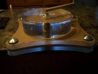
Not trying to derail the thread or anything but I thought I would share the deck I am building with the hopes of marrying to a really good motor/drive system.
The plinth is 1 inch acrylic top and bottom with 1/2 inch of aluminum in the center.
Still have some work in designing and making the tonearm mount and the motor housing.
All fun stuff.
The plinth is 1 inch acrylic top and bottom with 1/2 inch of aluminum in the center.
Still have some work in designing and making the tonearm mount and the motor housing.
All fun stuff.
Attachments
- Home
- Source & Line
- Analogue Source
- 3 Phase BLDC motor for turntable use?