Member
Joined 2009
Paid Member
my 2c Jaxbo8,
Jeff has a 'confident' personality - you gotta ride with the waves - then we'll have a good thread, otherwise this will go off the rails like many others
Jeff has a 'confident' personality - you gotta ride with the waves - then we'll have a good thread, otherwise this will go off the rails like many others
[...]Audio design is an ART and it requires LISTENING, not just calculating.[...]
Jeff,
I think you were the one asking about the audio circuit in post #354. I replied that it should basically work, and showed the very same circuit in #361 using some more common resistor values (not something like 52.767 kOhm..)
BUT not only that, and what YOU are UNAWARE of, compared to your proposal, with my resistor values and operating point, the 6GK5 driver tube will also be LESS THERMALLY STRESSED!! 😉😀😀 And this propagates thru the circuit and will be multiplied by the mu (- or better - gain) of the 6AH4GT power tube before reaching your speakers!! 😎😎
I appreciate you efforts to build these circuits, please follow up then and LISTEN and LEARN. 😉😉😛
Best
GB
Just the stuff about using REGS and other IC's.
No need for any IC's. Like I said, two MOSFETs for a simple reg. No IC.
A proper PSU will bring any other parts of the amp that may be lacking in fidelity to the front.
btw - every time I hear the words "fully balanced" I think "snake oil". I am not alone here.
Why is that? It's a topology; do you mean it can't really be balanced? Or that a balanced circuit by definition can't ever be all that good?
Op point is what really matters, but all other things (=curves) being equal;
Hotter bias = less higher harmonics = "better sound".
Of course not always. But if you were to make any general rule about heat and fidelity in tubes, it would be that more heat (more current) is better; buy some "good sound" with the expense of shorter tube life.
Hotter bias = less higher harmonics = "better sound".
Of course not always. But if you were to make any general rule about heat and fidelity in tubes, it would be that more heat (more current) is better; buy some "good sound" with the expense of shorter tube life.

Member
Joined 2009
Paid Member
I don't understand how the temperature of the plate affects the sound for the better or for the worse. I'm not saying somebody didn't perceive a difference, just that I don't know what physical reason might explain it. More current means higher transconductance and lower plate resistance which will affect the ability to drive the grid of the next stage I suppose and a higher current might simply be a better operating point regarding the 'curves'. But what's the deal with the temperature of the plate ?
The way manufacturers determine maximum tube dissipation is highly inconsistent: some can be highly conservative and others somewhat optimistic in their approach. This is evident from many of the experiments George 'Tubelab' has described on this forum. We all know of some tubes which can safely be pushed well beyond their specified limits and others which can barely reach specified maximum without significant plate glow.
Moreover, some tubes' maximum dissipation figures are specified for use in an extreme environment such as that of a vertical deflection amplifier in a TV. When used in an open well ventilated area, the tube's maximum safe dissipation can often be significantly higher.
These inconsistencies make it extremely problematic to attempt to specify a definitive optimum plate dissipation as a fixed percentage of the manufacturers' specified maximum.
Last edited:
No need for any IC's. Like I said, two MOSFETs for a simple reg. No IC.
Just out of interest, can you show us your fave topology? And why both transistors mosfets?
Of the four basic 2-tranny topologies, I found all to be lacking somehow either in noise, parts tolerances, or stability of regulation.
BR,
GB
goldenbeer:
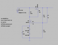
This is what I usually use. MOSFETs because I have them at hand. My main thing is headphones; even with RCRC (100 ohms 47µF 330 ohms 47µF) raw supply the B+ is completely quiet.
For SE, I would still look at better regs. This is more than adequate for balanced; it draws the same current down to nanoamperes at all times.
It gets the job done. No sonic penalties, no listening fatigue (even at headphones). Of course, it does bring up potential problems elsewhere more prominently, if there are problems.
Attachments
There remains the problem that the hum and noise of the B+ rail, injected at the cathode of the input tube is inter modulated with the input signal by the non-linear transfer curve of the input tube. It's one thing to have imperfect hum cancellation, but another to meddle with the signal. Thus providing another means for the power supply to influence the sound.
It's not intermodulated. The two remain separate circuits, with separate common references. You have to think of it more like using an input transformer to isolate ground loops.
Sheldon
Member
Joined 2009
Paid Member
Sheldon,
In my view of the circuit, the output tube is isolated as you and others have described. The output stage is 'ground referenced' to the B+ supply and not to the input signal ground. The speaker is isolated by the OPT and one side of the speaker can be referenced to signal ground without issue.
But in order to ensure the output stage is referenced to the B+ rail instead of signal ground you have to inject the B+ ripple / noise to the grid of the output tube at the right phase and amplitude. In this L-W circuit this is achieved by using the input tube to amplify a cut-down copy of the B+ noise injected at it's cathode.
The input tube amplifies the signal applied between its' grid and cathode which is both the input signal and the injected B+ noise. Any non-linearity in this triode will result in intermodulation of the two signals. It's theory. I acknowledge that nobody has found this to be a problem in practice - the sound is good from these amplifiers. I ran a simulation using Goldenbears file and looked at the IM - it's there but very small. Looks like a non-issue after all.
The input tube amplifies the signal applied between its' grid and cathode which is both the input signal and the injected B+ noise. Any non-linearity in this triode will result in intermodulation of the two signals. It's theory. I acknowledge that nobody has found this to be a problem in practice - the sound is good from these amplifiers. I ran a simulation using Goldenbears file and looked at the IM - it's there but very small. Looks like a non-issue after all.
Yes, I should have said "in practice", with attention to design details. Absolute perfection is not attainable. But as you say intermodulation is very small. In order to attain this, the input tube should be operated such that the mu is reasonably constant, which means a large load resistor and small cathode resistor (greater than 4 "triode factor").
That's why there are a limited number of combinations of input/output tubes that tick all the boxes without the follower and a reason why you don't see many using this topology (that and the fact that this design is not widely understood). With Darius's bootstrapped follower the load line is virtually horizontal - keeping the mu nearly constant, and allowing more flexibility with tube choices.
Sheldon
This is what I usually use. [...]
It gets the job done. No sonic penalties, no listening fatigue (even at headphones).
The basic 2 transistor regulator. I know it works and good to hear you like the sound.
There are however a few things i don't favor too much. HV zeners have huge component tolerances and temperature coeffs, it burns a lot oft power thru the zeners and Shunts, and of
 course it does pass the audio signal thru the mosfets..
Anyways, this thread is about audio circuits, not psus.
Thanks for posting.
GB
Or that a balanced circuit by definition can't ever be all that good?
As we all know, Pro audio is balanced by definition. It doesn't mean the gear is any better or worse though.
Balanced circuits are of course fine. Single ended circuits are also fine.
It is the "fully" adjective that I find troublesome. Many don't understand what this means.
For me, if your system is "fully" balanced it must meet this benchmark:
You take a balanced phono or CD input (for example) and amplify it in a balanced manner all the way through to the loudspeaker.
I frankly don't see any advantage in doing this, but I don't make "fully" balanced claims.
Ian
Last edited:
This thread is also decidedly about single ended circuits.
edit : maybe you are talking about a balanced headphone amplifier? taking balanced CD sound and amplifying it to your ears? that's easy enough to achieve. Not what goldenbeer started this thread about though...
edit : maybe you are talking about a balanced headphone amplifier? taking balanced CD sound and amplifying it to your ears? that's easy enough to achieve. Not what goldenbeer started this thread about though...
Last edited:
This thread is also not about metal oxide semiconductors.... But of course its Goldbeer's topic... if he likes it to go in this direction that's ok too.
Last edited:
goldenbeer:
This is what I usually use. MOSFETs because I have them at hand. My main thing is headphones; even with RCRC (100 ohms 47µF 330 ohms 47µF) raw supply the B+ is completely quiet.
For SE, I would still look at better regs. This is more than adequate for balanced; it draws the same current down to nanoamperes at all times.
It gets the job done. No sonic penalties, no listening fatigue (even at headphones). Of course, it does bring up potential problems elsewhere more prominently, if there are problems.
Where is the tube? I missed it in your schematic... I see you posting about metal oxide semiconductors, which are interresting since they are so nice and cheap.
I didn't think this thread was about headphone amps either, although I am certainly not againt them. 🙂
Last edited:
Jeff,
I think you were the one asking about the audio circuit in post #354. I replied that it should basically work, and showed the very same circuit in #361 using some more common resistor values (not something like 52.767 kOhm..)
BUT not only that, and what YOU are UNAWARE of, compared to your proposal, with my resistor values and operating point, the 6GK5 driver tube will also be LESS THERMALLY STRESSED!! 😉😀😀 And this propagates thru the circuit and will be multiplied by the mu (- or better - gain) of the 6AH4GT power tube before reaching your speakers!! 😎😎
I appreciate you efforts to build these circuits, please follow up then and LISTEN and LEARN. 😉😉😛
Best
GB
Thanks for posting !!
Thermal stress sonically, occurs when you run a tube appreciably over the Golden Ratio, which is 62%, and get up into the 80 % ratio or higher, in many cases, on Finals, in the 90+ %.
The 6GK5 we are discussing has a Maximum Plate Dissipation of 2.5 Watts rating. You are suggesting operating it at 0.628 Watts dissipation, and I at 0.882 Watts dissipation. Those ratios, Watts divided by 2.5 are : 25% ( yours ) and 35% ( mine) respectively, so, being well under the 62% Golden Ratio, thermal stress will hardly be an issue.
I LIKE either, the tube will last "long time" .... with either quiescent point.
Thanks for your kind response.
BTW, I "enjoyed" your idea of adding a small ( nF) tuning cap on the 6GK5 driver Rk in a two-stage LW circuit. That may have practical use.
Jeff Medwin
Member
Joined 2009
Paid Member
Thermal stress sonically, occurs when you run a tube appreciably over the Golden Ratio, which is 62%.
Then we should be running the likes of the JJ-2A3-40 at 24W plate dissipation or we're simply wasting headroom. At 24W we're at the Golden Ratio, no more and no less. And at 24W we may well be running in a more linear region of the curves.
There are however a few things i don't favor too much. HV zeners have huge component tolerances and temperature coeffs, it burns a lot oft power thru the zeners and Shunts, and of
Anyways, this thread is about audio circuits, not psus.
Zeners are a bit of a "try it out" thing in this case. Temp coeff is in my experience usually around 1 to 3 volts; in I practise I find zeners have no issues, since it's not a big deal if B+ is 305 V or 301 V.
The reg I posted as example burns around 3mA or so on shunts and zeners, depending on raw supply voltage. Not an issue in my experience.
As per audio signal: There is a 100% feedback loop around both FETs, at audio frequencies. A reg has "sonic effects" in so far as it lacks abilities. A 2.2 ohms output impedance reg sounds better, because it has lower output impedance than a 20 ohm reg.
100% feedback loop simply doesn't generate any harmonics (in any meaningful way in this audio context). No "sand sound". Added clarity will bring up other bottlenecks elsewhere in the circuit most surely.
I just thought to bring this up, since I was following this thread and there were quite a lot of messages regarding PSU design (specifically low output impedance, hence regs are relevant), so this thread was about PSU design before I came along. =)
Where is the tube? I missed it in your schematic... I see you posting about metal oxide semiconductors, which are interresting since they are so nice and cheap.
Not all PSUs have tubes. For example the one posted in post #357. There's nothing special about MOSFETs; they're components like chokes and caps. Chokes and caps are also not tubes and they're still discussed here. =)
Resistors are even cheaper. All of posted schematics have them as well. =)
I didn't think this thread was about headphone amps either, although I am certainly not againt them.
Yes. I brought that up only to demonstrate that (according to my experience) the reg I posted removes hum and noise so effectively, that it's ok even for headphone use (where noise is the most easily and most annoingly audible).
This thread is also decidedly about single ended circuits.
Yes I know. That's why I brought up twice that even though even a simple reg like I posted makes a lot of difference, for SE specifically I would look further. Perhaps a good (cheap and easy) starting point for experimentation.
It is the "fully" adjective that I find troublesome. Many don't understand what this means.
For me, if your system is "fully" balanced it must meet this benchmark:
You take a balanced phono or CD input (for example) and amplify it in a balanced manner all the way through to the loudspeaker.
I frankly don't see any advantage in doing this, but I don't make "fully" balanced claims.
I must specify; when I say "fully balanced", in this context, I mean that the device I am describing is fully balanced, it has only balanced gain stages. I brought it up because it is relevant when discussing regs; like I said, my amp draws in all situations the exact same current down to the nanoamperes. This is of course relevant for PSU and reg design.
Since this thread is not about SE v balanced, I will not go into that. I will mention, that one obvious benefit is the one described above; significantly relaxed PSU requirements. Even my 2 FET crappy reg is overkill; it's really there just to set the voltage.
Hi Jeff
Have you ever built a circuit with 6GK5? I have. It looked easy at first but quickly became frustrating.
Go look at the specs and plate curves.
Max plate voltage 200v so only useful for lower B+ W-L. I know how you like low B+....
Worse still, look at those plate curves - Kinda hard to figure out a linear load line with this little vacuum of wonder.
Ian
- Status
- Not open for further replies.
- Home
- Amplifiers
- Tubes / Valves
- 3 direct coupled 2A3 amps