Hello,
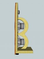
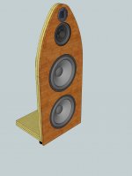
I have made a Sketchup model of a 3.5-way open baffle (attached) and would very much appreciate some comments and feedback on the baffle design itself.
The material used for the baffle, the base and the support stand will be three layers 22mm baltic birch with a vibration-reducing glue between, so thickness is 22 + 1 + 22 + 1 + 22 = 68mm.
The woofers are AE OB15. The upper one will cover 27 (Fs) to ~200Hz, the lower one 27 to ~100 Hz.
The midrange will be Supravox 215 Sig Bicone or Tang Band W8-1808.
The tweeter will be LCY-130 or BG Neo3. Looking for opinions on choice and xover freq but had 7-10kHz in mind, unless lower would sound better.
This will be an active system with DSP so relative driver sensitivity and physical time-alignment is not a major issue (I'm hoping).
Listening height is 1200mm (hence this dimension being indicated relative driver placement on the image).
Cheers
Attachments
-
 011 Efter basala dimensioner.jpg272.3 KB · Views: 389
 -
 010 Bakstycke efter sammanfogning med baffel(3).jpg305.7 KB · Views: 366
 -
 010 Bakstycke efter sammanfogning med baffel (4).jpg553.3 KB · Views: 355
 -
 010 Bakstycke efter sammanfogning med baffel (5).jpg510.6 KB · Views: 353
 -
 010 Bakstycke efter sammanfogning med baffel (6).jpg311.5 KB · Views: 341
 -
 010 Bakstycke efter sammanfogning med baffel (7).jpg173.2 KB · Views: 86
 -
 010 Bakstycke efter sammanfogning med baffel (8).jpg685.2 KB · Views: 79
Last edited:
will you truly have spl at your fs (27 hz) without something at the sides to extented the path length and avoid phase cancellation or change the shape of the base to a triangle so you can back them into a corner and let the room be your friend
I think so. A single OB15 in an infinite baffle is not reaching its Xmax (18.5 mm) at Fs (29 Hz) until input power of 400W and at a level of 114.4dB.
So if my baffle is down 18 dB from 240 Hz (assuming this is the xover freq), the single driver should be able to put out 96.4 dB. Two drivers another 3 dB, so 99.4 dB. Then if I sit 8 feet away, I lose 7.7 db due to dispersion/distance, so a total of 91.7 dB. This is without taking into account the room boundaries of course so perhaps +95 dB is achievable...?
So if my baffle is down 18 dB from 240 Hz (assuming this is the xover freq), the single driver should be able to put out 96.4 dB. Two drivers another 3 dB, so 99.4 dB. Then if I sit 8 feet away, I lose 7.7 db due to dispersion/distance, so a total of 91.7 dB. This is without taking into account the room boundaries of course so perhaps +95 dB is achievable...?
Last edited:
well i guess i have more to learn
i'm confused by your statement that "if my baffle is down 18 db from 240 hz"
i'm confused by your statement that "if my baffle is down 18 db from 240 hz"
How you intend to mount the Neo3 is an absolute no-go. The baffle is way too deep and - in my opinion - way too wide. Please look how others have integrated the Neo3 and follow them.
Find somebody who will simulate the OB15 for you in Martin J.Kings OB-worksheet. Just to make sure that your calculations hold true.
The vibration-reducing "glue" between stiff layers needs to be 2-3 mm thick to absorb vibrational energy. It would be better to just glue a 4 mm thick bitumen mat between two layers of 19 mm baltic birch and glue some tiles to the back of the OB.
Rudolf
So have I.
I was just trying derive how many decibel the two woofers will be down in my OB at Fs compared to an infinite baffle. If (i) the actively filtered woofers' passband covers the three octaves between 30-240 Hz, (ii) 114 dB is achievable at 240 Hz, and (iii) the OB roll-off is 6dB/octave - then they should be able to do 114 - (3 x 6) = 96 dB at 30 Hz (Fs). Then deducting for loss due to listening distance and adding for double drivers.
I was just trying derive how many decibel the two woofers will be down in my OB at Fs compared to an infinite baffle. If (i) the actively filtered woofers' passband covers the three octaves between 30-240 Hz, (ii) 114 dB is achievable at 240 Hz, and (iii) the OB roll-off is 6dB/octave - then they should be able to do 114 - (3 x 6) = 96 dB at 30 Hz (Fs). Then deducting for loss due to listening distance and adding for double drivers.
I don't see where your calculations account for different baffle width. I don't say that they can't be true, but you can't simply subtract 3 x 6 dB/oct from the max SPL in infinite baffle and be done.
NiToNi
an infinite baffle is an absolute! meaning that by it very nature there is no way for any of the energy from the rear of the speaker to reach the front (phase cancellation) this is not possible in the real world because even a closed box there is still the possibility that some of the energy from within is transmitted through the box it self (and in many cases the driver diaphragm itself) to the outside in an open baffle the low frequency limit is determined by baffle size. it's not to say your not going to reach that low it's just going to be way lower in amplitude then all other frequencies
i don't know what your expectations are but a flat response from 20 to 20000 is to the best of my knowledge not possible on an open baffle unless it's really big say the wall of your room(as your speaker mounting )
Hi,
You need to flare the rear openings of the mid and treble.
I've searched a lot on constrained layer damping, which works best with
only two layers and restrained layer damping (rear or front). The optimum
constrained layer I have yet to reasonably ascertain, but its not the same
as as an effective restraining layer, optimum seems to be quite different.
If you assume your baffle loss is -3dB at 240Hz, then 120 is -9dB,
60Hz -15dB and 30Hz -21dB. Side triangles could be quite useful.
rgds, sreten.
I'd suggest the effort and material in making mulit-layer baffle can be saved and used in separating mid-tweeter and woofers. And it would be more efficient in reducing vibration by soft supports rather than rigid structure. Thinner baffle is a plus in mid-high section.
About the woofers, since rear bracket is in plan, I'd suggest rear-mounting the drivers by moveable bracket holding/pressing the magnets onto the baffle.
Just my 2c. 🙂
About the woofers, since rear bracket is in plan, I'd suggest rear-mounting the drivers by moveable bracket holding/pressing the magnets onto the baffle.
Just my 2c. 🙂
Cheers, guys
That's the intention (rounded ~ 45 degrees) but I don't know how to do that in Sketchup, I've just been fiddling around with it for two days.
I had modelled the baffle for the LCY-130 but found a template in Trimble's database for a Neo3 with a faceplate, which is of the same diameter (130mm) so I just slotted it in for now. Just like the back plate, I guess the face plate on the Neo3 should not be used though when mounting it in an OB, right?
I know you are a big proponent of narrow baffles Rudolf, but to have them 60cm/24in wide by the woofers really helps with the bass extension. I also want some width around the midrange because I would like to have the possibility to run it full-range without support from the woofers (and tweeter) on occasion (such as when playing real-time on the keyboard when the >6ms latency introduced by the DSP filters is unacceptable) without it sounding too thin. The average baffle width on my design at midrange height is approx 45 cm, which is the same as a quite a few other baffle implementations I have seen of 8-inch fullrange drivers (Thorsten, ChilL, JE Labs etc). Its roll-off should begin at 200-250 Hz.
The narrowing towards the top is an attempt at reducing the surface area around the tweeter though. I have looked at other implementations and several of them have quite a lot of baffle estate around them, for example:
Super7
EVS-2
What if I only use two instead of three sheets of plywood for the tweeter and midrange section, so the third sheet ends between the upper woofer and the midrange? Also, remember chamfering is not modelled in so both the tweeter and the mid will radiate much wider and openly than on the illustrations.
What is your view though on going with the monopol LCY-130 ribbon (that I already own) instead of the Neo3 (which I don't own)? Is it crucial to have dipol radiation also from the tweeter, particularly if the xover freq ends up as high as 7-10kHz? I've seen arguments both ways and feel a bit lost on this still TBH...
Noted. So you're also suggesting that I should try to stick to two instead of three layers of plywood in my sandwich construction?
The "glue" I will use is made by Swedac and builds 1 mm when applied according to their instructions. A sandwich with bitumen sounds like a good idea, I'll look into that too, but suspect it'd be a relatively pricey solution. Besides, I've bought the glue already.
I had assumed 0 dB baffle loss in my example, sorry I should've said. I'd like to give a flat wing-less design a go to begin with since quite a few people have commented on them having this special magic to them - and I'm a huge Maggie fan myself 😱
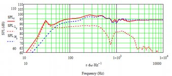
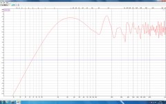
No I agree, I was a bit off in my example. Like I said, I should have mentioned I had assumed no baffle loss at 240 Hz and that I then just super-imposed a normal 6dB/octave roll-off on the drivers know infinite baffle response. Edge models the two woofers to be down by 13 dB at Fs. MJK's spreadsheet says the bass response is 85dB @ 1W, or 111dB @ 400W. Both quick-and-dirty simulations are attached. The MJK is not entirely accurate since I'm missing Bl value for the OB15 (explaining the bump at Fs?) and Le value for the Supravox. Further, a rectangluar baffle is assumed with no narrowing like in the Sketchup model. Also, no xover is assumed.
In either case, I'm fairly comfortable these four woofers (driven by a ICEpower 1000ASP per woofer) will move enough air in my room. I am more worried by the SPL capability of the FR to be honest, or even more so the Neo3 (10W RMS!) would I decide to swap it for the LCY-130.
Gotcha
You need to flare the rear openings of the mid and treble.
That's the intention (rounded ~ 45 degrees) but I don't know how to do that in Sketchup, I've just been fiddling around with it for two days.
How you intend to mount the Neo3 is an absolute no-go. The baffle is way too deep and - in my opinion - way too wide. Please look how others have integrated the Neo3 and follow them.
I had modelled the baffle for the LCY-130 but found a template in Trimble's database for a Neo3 with a faceplate, which is of the same diameter (130mm) so I just slotted it in for now. Just like the back plate, I guess the face plate on the Neo3 should not be used though when mounting it in an OB, right?
I know you are a big proponent of narrow baffles Rudolf, but to have them 60cm/24in wide by the woofers really helps with the bass extension. I also want some width around the midrange because I would like to have the possibility to run it full-range without support from the woofers (and tweeter) on occasion (such as when playing real-time on the keyboard when the >6ms latency introduced by the DSP filters is unacceptable) without it sounding too thin. The average baffle width on my design at midrange height is approx 45 cm, which is the same as a quite a few other baffle implementations I have seen of 8-inch fullrange drivers (Thorsten, ChilL, JE Labs etc). Its roll-off should begin at 200-250 Hz.
The narrowing towards the top is an attempt at reducing the surface area around the tweeter though. I have looked at other implementations and several of them have quite a lot of baffle estate around them, for example:
Super7
EVS-2
What if I only use two instead of three sheets of plywood for the tweeter and midrange section, so the third sheet ends between the upper woofer and the midrange? Also, remember chamfering is not modelled in so both the tweeter and the mid will radiate much wider and openly than on the illustrations.
What is your view though on going with the monopol LCY-130 ribbon (that I already own) instead of the Neo3 (which I don't own)? Is it crucial to have dipol radiation also from the tweeter, particularly if the xover freq ends up as high as 7-10kHz? I've seen arguments both ways and feel a bit lost on this still TBH...
I've searched a lot on constrained layer damping, which works best with only two layers and restrained layer damping (rear or front). The optimum constrained layer I have yet to reasonably ascertain, but its not the same as as an effective restraining layer, optimum seems to be quite different..
Noted. So you're also suggesting that I should try to stick to two instead of three layers of plywood in my sandwich construction?
The vibration-reducing "glue" between stiff layers needs to be 2-3 mm thick to absorb vibrational energy. It would be better to just glue a 4 mm thick bitumen mat between two layers of 19 mm baltic birch and glue some tiles to the back of the OB.
The "glue" I will use is made by Swedac and builds 1 mm when applied according to their instructions. A sandwich with bitumen sounds like a good idea, I'll look into that too, but suspect it'd be a relatively pricey solution. Besides, I've bought the glue already.
If you assume your baffle loss is -3dB at 240Hz, then 120 is -9dB, 60Hz -15dB and 30Hz -21dB. Side triangles could be quite useful.
I had assumed 0 dB baffle loss in my example, sorry I should've said. I'd like to give a flat wing-less design a go to begin with since quite a few people have commented on them having this special magic to them - and I'm a huge Maggie fan myself 😱
I don't see where your calculations account for different baffle width. I don't say that they can't be true, but you can't simply subtract 3 x 6 dB/oct from the max SPL in infinite baffle and be done. Find somebody who will simulate the OB15 for you in Martin J.Kings OB-worksheet. Just to make sure that your calculations hold true.
No I agree, I was a bit off in my example. Like I said, I should have mentioned I had assumed no baffle loss at 240 Hz and that I then just super-imposed a normal 6dB/octave roll-off on the drivers know infinite baffle response. Edge models the two woofers to be down by 13 dB at Fs. MJK's spreadsheet says the bass response is 85dB @ 1W, or 111dB @ 400W. Both quick-and-dirty simulations are attached. The MJK is not entirely accurate since I'm missing Bl value for the OB15 (explaining the bump at Fs?) and Le value for the Supravox. Further, a rectangluar baffle is assumed with no narrowing like in the Sketchup model. Also, no xover is assumed.
In either case, I'm fairly comfortable these four woofers (driven by a ICEpower 1000ASP per woofer) will move enough air in my room. I am more worried by the SPL capability of the FR to be honest, or even more so the Neo3 (10W RMS!) would I decide to swap it for the LCY-130.
an infinite baffle is an absolute! meaning that by it very nature there is no way for any of the energy from the rear of the speaker to reach the front (phase cancellation) this is not possible in the real world because even a closed box there is still the possibility that some of the energy from within is transmitted through the box it self (and in many cases the driver diaphragm itself) to the outside in an open baffle the low frequency limit is determined by baffle size. it's not to say your not going to reach that low it's just going to be way lower in amplitude then all other frequencies
i don't know what your expectations are but a flat response from 20 to 20000 is to the best of my knowledge not possible on an open baffle unless it's really big say the wall of your room(as your speaker mounting )
Gotcha
Attachments

I'd suggest the effort and material in making mulit-layer baffle can be saved and used in separating mid-tweeter and woofers. And it would be more efficient in reducing vibration by soft supports rather than rigid structure. Thinner baffle is a plus in mid-high section.
About the woofers, since rear bracket is in plan, I'd suggest rear-mounting the drivers by moveable bracket holding/pressing the magnets onto the baffle.
What I hadn't mentioned, and what's not visible on the model, is that it's only the tweeter and the mid which are attached to the first/front plywood sheet on the baffle. The woofers are mounted on the second/middle sheet without touching the front sheet physically. So the MT and the front sheet is "floating" on a layer of the green glue (this product is actually blue in colour though) on top of the middle sheet that holds the WW. This way I hope to reduce some of the WW-borne vibrations to the MT without messing with magnet mounting or seperate baffles etc.
Does that make sense...?
Sounds good, but please forgive my ignorance about the green glue. I have no idea how good it can 'float' the baffle(s).
I just brought up some ideas of efficient build - less effort and material with equally good or even better outcomes. For vibration issue, the best solution I know is suspension - hanging the drivers with wire/rope/rubber bands ... etc.
Search 'swing' in this forum and you'll see several examples which are almost free from any vibration -- not just reduced vibration, it's almost none. Seeing a 18" cone moving several mm with totally calm frame (in touch with fingers) is an amazing experince. A rigid structure (even a boxed speaker) with the same ability would be much much much heavier (inefficient).
Of course there're many other aspects in designing a speaker. Feel free to assemble your own combinations. 🙂
If you have already read JohnK's Music and Design site and the Linkwitz Lab site then you know that musical magic can only be achieved from 4-way dipole speakers with controlled directivity from crossing a wave-guide directed dipole tweeter to a ~4" upper midrange, plus a 8"-10" lower midbass, plus 10"-15" dipole woofers in a "folded baffle"(H,W,M,U). The measured polar response from this 4-way arrangement is exceptional.
I own Lambda TD15Dipoles and favor a 16" deep H-frame with one speaker cone facing forward and one rearward. I added a base-cavity that can hold ~20 pounds of sand to control vibration. A folded baffle really helps deep bass production. Vibration isolation for the MmT baffle is helpful.
For dipoles I favor a 10" midbass over an 8". A 10" midbass can cover 100Hz with low IM distortion, and most have 90 degree polar response ~1000Hz. I've built wide dipole ribbon tweeters that could be crossed at 1000Hz, but they sound "thin". I'm currently learning from JohnK and Linkwitz about adding a 4" upper midrange and crossing a dipole pair of small diameter dome tweeters ~3500Hz.
I own the Tang Band W8-1808 and would recommend a 200Hz xover to stay within the 5mm X-max when used as a dipole. I would not use the W8-1808 full range and would add a dipole tweeter.
"magic can only be achieved........"
Really???
Can you put numbers to IM distortion for 8" v 10" midbass?
Andrew
Really???
Can you put numbers to IM distortion for 8" v 10" midbass?
Andrew
"magic can only be achieved........"
Really???
Andrew
Hi Andrew,
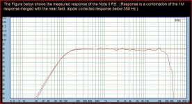
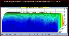
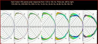
I copied JohnK's recent Nano Note2 data to help show what musical magic looks like in measurement to me. You should go to the Music and Design website for JohnK's white papers on why a 4-way dipole is necessary for the polar response shown.
Dipole speakers are often praised for how the figure-8 radiation pattern reduces room effects, as well as how dipoles remove box speaker panel resonance artifacts. JohnK and Linkwitz have measurement and listening studies that indicate that controlled dipole polar response from low bass to high treble should also be praised.
If you read the back-in-the-day literature you quickly realize how far dipole knowledge has progressed from putting a speaker into a 24" x 48" sheet of plywood and claiming musical magic.
Attachments
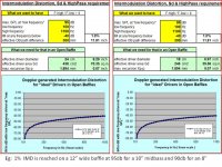
Barleywater;3226088 Can you put numbers to IM distortion for 8" v 10" midbass? Andrew[/QUOTE said:There are a few tools that allow quick rough estimates for dipole driver IMD based upon the baffle size, frequency range, SPL, and driver size. Obtaining a controlled polar response often requires small baffle area, and this naturally increases IMD from greater low frequency Xmax demands.
Attachments

Have you validated your modeling tool with real measurements?
Pluto Clone, 2-way frequency response:
Near field, and 42" gated measurements may be merged to get result very similar to John's FR:
I don't have software, and don't take time to do detailed off axis behavior, but:
So, two-way omnidirectional performs same basic magic. Putting a rear firing tweeter on setup would yield symmetrical front/back performance. Radiation 45-90 degrees at low frequencies has little impact on imaging, these cues are acquired by brain from first 3ms of transients. When early reflections have same spectral content as direct sound, it is easier for brain to parse them out as redundant information, making it easier to accept phantom image as real.
This is the magic, and it didn't magically vanish from my house when John K and SL put together 4-way dipoles. Don't get me wrong, these guys do great work.
I'm just not convinced that small dipole emulating point source has advantage over similar omnidirectional design. For given driver size, excursion and thus IMD will be lower for closed baffle. The rest is just EQ.
For line source, dipole in my opinion makes perfect sense for domestic use.
Regards,
Andrew
Pluto Clone, 2-way frequency response:
Near field, and 42" gated measurements may be merged to get result very similar to John's FR:
An externally hosted image should be here but it was not working when we last tested it.
An externally hosted image should be here but it was not working when we last tested it.
I don't have software, and don't take time to do detailed off axis behavior, but:
So, two-way omnidirectional performs same basic magic. Putting a rear firing tweeter on setup would yield symmetrical front/back performance. Radiation 45-90 degrees at low frequencies has little impact on imaging, these cues are acquired by brain from first 3ms of transients. When early reflections have same spectral content as direct sound, it is easier for brain to parse them out as redundant information, making it easier to accept phantom image as real.
This is the magic, and it didn't magically vanish from my house when John K and SL put together 4-way dipoles. Don't get me wrong, these guys do great work.
I'm just not convinced that small dipole emulating point source has advantage over similar omnidirectional design. For given driver size, excursion and thus IMD will be lower for closed baffle. The rest is just EQ.
For line source, dipole in my opinion makes perfect sense for domestic use.
Regards,
Andrew
"big proponent of narrow baffles" doesn't do me justice 😉.I know you are a big proponent of narrow baffles Rudolf, but to have them 60cm/24in wide by the woofers really helps with the bass extension.
60 cm for a woofer baffle is perfectly ok. I'd prefer a H frame with even more effective baffle width. My concern is solely with the upper drivers, where baffle width gets in conflict with a good dipole radiation pattern.
I understand your choice after knowing more about your implementation and needs. 🙂I also want some width around the midrange because I would like to have the possibility to run it full-range without support from the woofers
Apparently not every OB has a good dipole pattern as a main design requirement. 😉
My main concern was about the deep tunnel behind the Neo3. I learnt that it was a Sketchup problem only. But using all three sheets only in the woofer department makes sense to me nevertheless.What if I only use two instead of three sheets of plywood for the tweeter and midrange section, so the third sheet ends between the upper woofer and the midrange? Also, remember chamfering is not modelled in so both the tweeter and the mid will radiate much wider and openly than on the illustrations.
I'm not too narrow minded in this regard. Much depends on the reflective properties of the room. If you find the LCY-130 lacking in any way (which need not be so), you can still change to the Neo3.What is your view though on going with the monopol LCY-130 ribbon (that I already own) instead of the Neo3 (which I don't own)? Is it crucial to have dipol radiation also from the tweeter, particularly if the xover freq ends up as high as 7-10kHz?
As I have learned, vibrational energy in the baffle sheets will be dissipated by shear in the viscous layer between them. 1 mm thickness wouldn't allow for much shear though. I was thinking about some anti-drone mat from the automotive sector. Those are quite affordable over here and don't need messing around with a hot flame. 😱The "glue" I will use is made by Swedac and builds 1 mm when applied according to their instructions. A sandwich with bitumen sounds like a good idea, I'll look into that too, but suspect it'd be a relatively pricey solution. Besides, I've bought the glue already.
Rudolf
So, two-way omnidirectional performs same basic magic.
I have Plutos in my bedroom system and they took the Pluto+ upgrade to get reasonable (not what I have in the main system with Orions and 14.5" sub-woofer for home theater) output levels which makes them a 3-way system.
Putting a rear firing tweeter on setup would yield symmetrical front/back performance.
And degraded on-axis performance, because baffle step is around 2.5Khz and you're going to get cancellation unless you move the drivers closer to the center of the mid-woofer at which point you get reflections off its cone.
The dipole's symmetrical front/rear radiation probably isn't a feature (wave guides matched to ~12" midrange drivers work great without it) it's just something you live with to get better behavior in the first reflections spectra especially the ones closer than the front-wall.
I'm just not convinced that small dipole emulating point source has advantage over similar omnidirectional design. For given driver size, excursion and thus IMD will be lower for closed baffle. The rest is just EQ.
The dipole preserves fine musical texture farther into the room and does a better job preserving the bass envelope. It does that fitting into a narrower package than a wave guide which doesn't preserve directivity as low but at the expense of cost (you need 4X the displacement of a box speaker at 40Hz and probably one more driver + cross-over) and complexity.
- Status
- Not open for further replies.
- Home
- Loudspeakers
- Multi-Way
- 3.5-way open baffle Sketchup model: Comments please