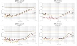
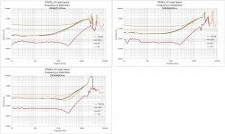
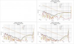
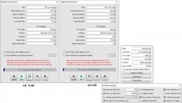
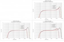
Step Frequency distortion
192kHz sampling rate. No LP filter btn dummy load and AR
192kHz sampling rate. No LP filter btn dummy load and AR
Attachments


Nice work but since people are always connected through the buffer board, it would of been more useful with the buffer board included. I understand that with or without buffer board will lead different results.
Thanks
Eric
Thanks
Eric
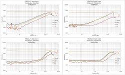
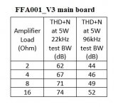
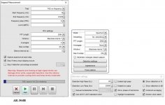
Thanks for the work!! What value is the 5 watt SINAD. I know that measurement isn't super important but since it's used on other sites it would give us a some sort of gauge for comparison.Step Level distortion.
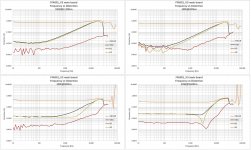
44.1kHz sampling rate. A passive 33.7kHz 12dB/oct LP filter btn dummy load and AR
Thanks again!
Scott
Last edited by a moderator:
Thank you Scott
The SW I use does not extract SINAD numbers.
That said, for a given input frequency and amplitude, SINAD is equal to THD + N, provided the bandwidth for the noise measurement is the same for both (the Nyquist bandwidth).
https://www.analog.com/media/en/training-seminars/tutorials/MT-003.pdf
From my measurements, using a test signal of 997Hz, I can give you tabulated THD+N numbers (small attachment).
You can check the THD+N @22kHz test bandwidth at any output power and load from the diagrams I have provided in #520 post, 3rd attachment.
When comparing results of equipment tests, please always check the test BW of each.
Hi Eric
I have made measurements of the RCA buffer+mainboard. I need some time to bring them into presentable form
George
Attachments
Not a peep from Eric, hope he survived his holiday. Here in the US they only give us a few days vacation at a time because they know we probably won’t come back if we have too much fun.
Bill
Bill
@George, with a larger input coupling cap value, I am getting an audible pop upon turn on. Have you experienced this ?Thank you zoom.
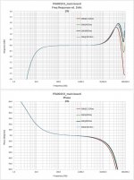
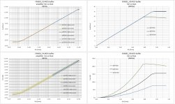
Now the low bass can be improved by increasing the capacitance of the two 22uF bypolar electrolytic caps found close to the multipin connector on the main board. The easy way is to parallel some bypolars by soldering them across the pins of the existing caps at the underside of the board.
I didn't have bypolars. I tested with back to back polar electrolytics.
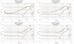
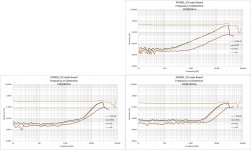
1st diagram is freq response at low end. 2nd diagram is phase, 3rd is group delay.
Light brown is with the stock 22uF.
Blue is with an added 50uF (total 72uF).
Red is with an added 100uF (total 122uF).
George
Hi zoom
This is typical when increasing the C.
With an added 50uF I don't notice it.
With 100uF and more, yes.
I had measured the non audible ac thumb with the stock 22uF (measurements across speaker terminals@8Ohm, see attachment). I haven't meaured it with added capacitance.
George
This is typical when increasing the C.
With an added 50uF I don't notice it.
With 100uF and more, yes.
I had measured the non audible ac thumb with the stock 22uF (measurements across speaker terminals@8Ohm, see attachment). I haven't meaured it with added capacitance.
George
Attachments
Last edited:

Hi, BillNot a peep from Eric, hope he survived his holiday. Here in the US they only give us a few days vacation at a time because they know we probably won’t come back if we have too much fun.
Bill
Thanks for your caring 😀
I only take one week to rest and am busy with work now.
The virus seems to have disappeared entirely here after the CNY, and we're working hard to catch the schedule from many customers.
And, I'll keep the eye on this thread and promise to get your question answered.
Thanks ,Eric
Thanks George for your contribution and knowledge sharing for the friends.Thank you Scott
The SW I use does not extract SINAD numbers.
That said, for a given input frequency and amplitude, SINAD is equal to THD + N, provided the bandwidth for the noise measurement is the same for both (the Nyquist bandwidth).
https://www.analog.com/media/en/training-seminars/tutorials/MT-003.pdf
From my measurements, using a test signal of 997Hz, I can give you tabulated THD+N numbers (small attachment).
You can check the THD+N @22kHz test bandwidth at any output power and load from the diagrams I have provided in #520 post, 3rd attachment.
When comparing results of equipment tests, please always check the test BW of each.
Hi Eric
I have made measurements of the RCA buffer+mainboard. I need some time to bring them into presentable form
George
If sth I can do for you, just drop the message.
Thanks,Eric
Thank you Eric.
I will mess the things up and you will do the cleaning
Your three modules are paying their service to the music, the forth is on the bench (tough boy)
George
I will mess the things up and you will do the cleaning
Your three modules are paying their service to the music, the forth is on the bench (tough boy)
George
Thanks for your continued love of this module, and glad to know it can survive a lot of your torture tests 😀 👍
Thanks,Eric
Thanks,Eric
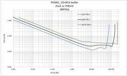
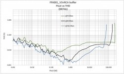
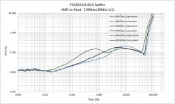
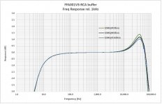
I had spoken of some measurements on the FFA001_V3 + RCA buffer that e_fortier asked for .
These were actually made two weeks before those of the main board I have shown in posts #518 to #522 and were of another’s module unit. They remained as raw data for the time being.
Measurements at 2Ohm load had not been taken then.
In general these measurements -par the input voltage and amplifier gain- don’t differ from what I have shown so far.
I can say that the RCA buffer does not degrade the performance of the main board measurement wise.
Anyway, here it goes:
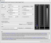
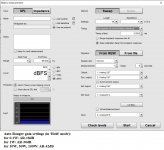
Amplifier in stock form (one channel only) driven from the line-out of an EMU 0404 soundcard.
Load is a home made set of dummy load power resistors.
Vout goes to Jan Didden's Autoranging attenuator (manual mode) and from there to soundcard's input.
Software is REW. The measurement files are exported to MS Excel for convenient and uniform presentation.
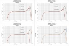
Vout, Pout, gain, linearity.
44.1kHz sampling rate. A passive 33.7kHz 12dB/oct LP filter btn dummy load and AR
These were actually made two weeks before those of the main board I have shown in posts #518 to #522 and were of another’s module unit. They remained as raw data for the time being.
Measurements at 2Ohm load had not been taken then.
In general these measurements -par the input voltage and amplifier gain- don’t differ from what I have shown so far.
I can say that the RCA buffer does not degrade the performance of the main board measurement wise.
Anyway, here it goes:
Amplifier in stock form (one channel only) driven from the line-out of an EMU 0404 soundcard.
Load is a home made set of dummy load power resistors.
Vout goes to Jan Didden's Autoranging attenuator (manual mode) and from there to soundcard's input.
Software is REW. The measurement files are exported to MS Excel for convenient and uniform presentation.
Vout, Pout, gain, linearity.
44.1kHz sampling rate. A passive 33.7kHz 12dB/oct LP filter btn dummy load and AR
Attachments


Last edited:
Step Level distortion.
44.1kHz sampling rate. A passive 33.7kHz 12dB/oct LP filter btn dummy load and AR
44.1kHz sampling rate. A passive 33.7kHz 12dB/oct LP filter btn dummy load and AR
Attachments


Put in small box, I'm quite please with the result. I take rca out and wire with volume pot and selector switch.

Eric,
Any progress on FFA003 amp? I am in the process of building the Wolverine amp, It will be an interesting comparison.
Bill
Any progress on FFA003 amp? I am in the process of building the Wolverine amp, It will be an interesting comparison.
Bill
- Home
- Vendor's Bazaar
- 2x150W Amp module for sale