Good to hear the link works now Andrew.
I made a diagram of my proposed modification to my existing audiosector lm3875-pcb:
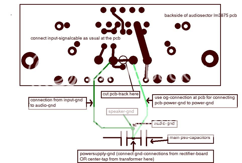
In my experiment offset from audio-gnd to ps-gnd is minimal
(caused by soldering of various connections to ps-gnd)
Hope this makes everything clear.
With kind regards,
Klaas
I made a diagram of my proposed modification to my existing audiosector lm3875-pcb:
In my experiment offset from audio-gnd to ps-gnd is minimal
(caused by soldering of various connections to ps-gnd)
Hope this makes everything clear.
With kind regards,
Klaas
Hi Kv,
what currents (components) are running through the pale green ground link?
I would connect the pale green link to the audio ground not the PSU common as shown in your diagram.
Try to ensure that the PSU common, main smoothing caps, rectifiers and transformer flow & return form their own small loops that DO NOT use any other ground links. This keeps the charging pulses IN the loops and by keeping the loop areas small, reduce electromagnetic radiation influences. Short and compact really works in this charging circuit.
There should be a discrete link between PSU common and audio ground. It can be short (or longer) but the two must not be allowed to "merge" into each other.
It may be that your link always did work, but sometimes my broadband slows down so much that the PC times out and tells me no link. I tried it twice. then saw El's reply so tried both his and your's again still failure. Then some minutes later it linked. Confusing this PC stuff. Grounding is easy in comparison.
Although again I admit that for decades I could make no sense of it until reading JLH & Leach & joining this forum, then it all fell into place.
I think it helps if we can forget the general name "ground" and adopt different names for each of the commons, earths, 0V references etc. Then think what each is doing. That's where/when I started to see the logic.
Andrew, my diagram doesn't make this clear, but on pcb are still 2x1500 uF panasonic capacitors.
So light-green connects their common connection (at pcb) to psu-gnd.
I agree with you on the subject of naming various connections, it can make things unclear.
I'm not really good at naming various gnd-connections myself.
That's why i started drawing, i think it makes understanding easier for a lot of people.
Let me know what you think regarding my efforts, i know there's room for improvement - the more i learn, the more i know there's still a lot to learn.
Thanks,
Klaas
Hi Kv,
the two remaining on board caps sound like decoupling caps.
Yes, you made the correct decision to take the decoupling cap common separately to the audio ground.
Are there any other components on the PCB that may have dirty/contaminated signals or high currents in their return legs?
I realise that with chipamps your hands are tied (behind your back) and you have to take what the chip designer gave you.
Some of the digital chips now have separate grounds from various parts of the circuits, each getting best coupling to a reference.
Maybe some/all of the analogue/linear designers might start copying this practice. Maybe there are one or two examples already out there.
I believe that often the difference in performance between discrete and integarted comes down to the external connections.
Thanks again Andrew .
you said:
Yes, you made the correct decision to take the decoupling cap common separately to the audio ground.
Just to make things more clear: i connected decoupling cap common separately to ps-gnd.
I'll work on a new diagram.
With kind regards,
Klaas
you said:
Yes, you made the correct decision to take the decoupling cap common separately to the audio ground.
Just to make things more clear: i connected decoupling cap common separately to ps-gnd.
I'll work on a new diagram.
With kind regards,
Klaas
Hi Kv,
i note that your diagram shows decoupling to PSU common.
I deliberately said to audio ground.
Now I'll explain my reasoning.
The PSU common will have significant charging pulses through it. One connection going to audio ground may not be, electrically, identical to a second connection going to decoupling common.
If there is a finite resistance between the two connection points on the PSU common then there will be a voltage difference between the two connections.
Now lets assume that the 0V referencce provided by the audio ground is fixed at 0V exactly, it is our reference after all.
Now we know there is a voltage difference between decoupling common and 0V reference.
This voltage difference (consisting substantially of pulses) will be fed along the link to decoupling common.
The live side of the decoupling caps will respond to the varying voltage on the decoupling common.
This voltage coming through the decoupling caps is now adding to any artefacts on the supply rails.
The purpose of the decoupling is to attenuate variations on the supply rails.
Connecting the decoupling common to the PSU common adds variations to the supply rails.
Where should decoupling common link to?
I think you know the answer, this could be teacher/pupil feedback.
I need some feedback (from anyone still listening) because my whole grounding philosophy is based on similar logic.
Indeed an identical argument determines why the central star ground (audio ground) MUST NOT be connected to the common plate interconnecting the smoothing cap commons and worse, multiple connections to that common plate. This bad practice is repeated regularly by designers and builders who should know better.
Hi,
One thing I am fairly sure about:- It would take one heck of a complicated model to get a simulator to help predict what's better for the sound quality.
good question, I suppose it's down to test and measure, maybe even listen.where does decoupling stop and ps-capacity start
One thing I am fairly sure about:- It would take one heck of a complicated model to get a simulator to help predict what's better for the sound quality.
To answer your question, Andrew:
I think that decoupling-gnd (without getting into an endless debate to answer my last question) should be connected to audio-gnd.
Why ?
Because you want ps-rails as clean as possible .
As clean as possible to your ultimate reference: audio-gnd.
I hope this reasoning answers your question.
If or if not, please let me know.
With kind regards,
Klaas
Andrew, i've been thinking.
Can we agree on the fact that if you SIGNIFICANTLY increase value of "decoupling caps" there will be a point where contamination of audio-gnd by the charging-pulses of "decoupling caps" exceeds the variation on the ps-rails caused by the connection of "decoupling caps" to ps-gnd ?

Klaas
Can we agree on the fact that if you SIGNIFICANTLY increase value of "decoupling caps" there will be a point where contamination of audio-gnd by the charging-pulses of "decoupling caps" exceeds the variation on the ps-rails caused by the connection of "decoupling caps" to ps-gnd ?
Klaas
Hi Kv,
you're too good with the difficult questions.
I'm not going to answer directly but instead pose a few senarios.
If the DC on the PSU rails is reasonably clean then you are feeding clean power to the decoupling caps. Then the decoupling caps can do their jobs. Firstly to compensate for inductance in the supply routes and give quick low level recovery to try to keep the voltage on the PCB rails reasonably flat. Secondly as a bypass cap so that sudden current demand on the PCB is first absorbed into the decoupling caps so that the hole in the current supply is refilled by the cap. If the decoupling is correctly sized and quick enough then I think it would be better to keep decoupling common on the audio ground, mostly due to clean supply from the smoothing caps.
Second senario, rough smoothing at the first stage sending a significant ripple to the PCB and the decoupling caps of less capacitance than first stage smoothing. This is effectively RCRC with a little bit of L combined with each C. I am sure someone could analyse this on a simulator when feeding both ClassA and ClassAB amps. Here there could be an argument for moving the decouple to the PSU common, but I am inclined to think it's better left on the audio ground.
Third senario, decoupling caps larger than first stage smoothing. This is definitely into RCRC supply with the last stage local to the PCB (onboard). I suspect that here the decoupling caps are actually part of the PSU and the common should be on the PSU common. Since the second stage is on board then secondary decouple can probably be dispensed with. Although there may be a case to install very local decoupling for some of the low current stages and bypasses around very high current devices.
If this last senario is really a two stage PSU with both stages best taken to PSU common then your question becomes more relevant. When does it become better to revert to keeping the decoupling common on the audio ground?
I cannot answer that at my stage of electronics knowledge. I bet there are others here that could offer an informed opinion.
It just occured to me that this fits the model I used some months ago referring to:- power ground (PSU common), dirty ground, high current ground, clean ground (signal ground), digital ground anciliaries ground (relays etc). Make some sense out of that if you prefer.
Andrew, sorry about taking my time to reply, but you've given me a lot to think about.
I guess we're a bit stuck here, if noone else comes along with an educated opinion.
I'm afraid i dont have enough knowledge right now to either challenge your reasoning or confirm it.
My reasoning (belief ?) regarding the subject of separate grounding for filtering-caps is largely based on the opinion of others more knowledgeable than me AND empirical "evidence" (my ears).
It appears to me i have some reading to do on this subject: Can you advise me some good book(s) covering this subject ?
With kind regards,
Klaas
Hi,
Self and Leach both address this, but detailed and reliable information is scant judging by my research.
There are many sources that re-iterate that decoupling caps should be kept off the clean ground. But can that be relied on?
Seems we have talked the opposition to a standstill.
I do wish they had something to say, even a counter argument would give us something to chew on.
Typical decoupling caps are usually 10nF or 100nF ceramic. They keep RFI and EMI off the chip at the junction of the power supply rail power pin. Good for analog design by all means but note this -- the trace from the ground side of the cap to the central ground locus should be as sort as possible. Elsewise you just make another radiator or antenna to pick up more birdies.
Hi Jack,
we are talking the bigger decoupling eletrolytics on the PCB.
Your little caps might more appropriately be called bypass. Intended to attenuate the glitches causes by a sudden change in current at devices.
Thanks for your input, it helps not to get too parochial.
BTW. I have opened a rectifier thread in PSU asking a similar question
Perhaps, you could go there and help me out by offering an opinion?
- Status
- This old topic is closed. If you want to reopen this topic, contact a moderator using the "Report Post" button.
- Home
- Amplifiers
- Chip Amps
- 2x LM4780 + DRV134 = hum Need grounding help!