AndrewT said:I suggest you remove the smoothing cap common from the audio ground and remove the transformer centre tap from the audio ground.
Connect transformer centre tap to smoothing cap common.This figure of eight loop from transformer to rectifier to smoothing caps and all the way back to the transformer should be as compact as possible and all the wires in these loops should be as close together as possible to minimise "loop area".
Connect this new PSU common using a single wire link to the audio ground.
Yeah I tried this too but still slight buzz. The whole amp was a little "rushed" so the connections etc are less than ideal in length and placement so I will put it down to that. I'm gonna dismantle is anyway and make it into two amps
")
Thank you kindly everyone for your suggestions!
I can't tell for sure from your photo but it appears the shielded cable from the RCA's is grounded at both end. If that is the case remove the shield from ground at the end farthest from the input.
A shielded cable grounded at both ends is often worse than no shielded cable at all.
Also if your speaker binding posts are grounded to the chassis fix that as well. don't ground the binding posts.
A shielded cable grounded at both ends is often worse than no shielded cable at all.
Also if your speaker binding posts are grounded to the chassis fix that as well. don't ground the binding posts.
Sherman said:I can't tell for sure from your photo but it appears the shielded cable from the RCA's is grounded at both end. If that is the case remove the shield from ground at the end farthest from the input.
No, it was only grounded at one end and I tried it without the shield connected too.
Indeed it is! I have had this problem before.Sherman said:A shielded cable grounded at both ends is often worse than no shielded cable at all.
Nope, they were directly connected to the PCB. I don't think it could have worked with one speaker terminal connected to GND anyway due to how the DRV134 works.Sherman said:Also if your speaker binding posts are grounded to the chassis fix that as well. don't ground the binding posts.
Thanks though!
maxw said:
No, it was only grounded at one end and I tried it without the shield connected too.
Indeed it is! I have had this problem before.
Nope, they were directly connected to the PCB. I don't think it could have worked with one speaker terminal connected to GND anyway due to how the DRV134 works.
Thanks though!
Darn! Now I'm out of ideas.

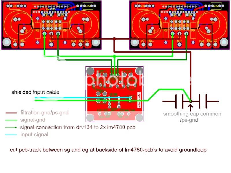
Maxw, sorry for my late reply. Can you confirm you're running your amplifier without signal-gnd connection from the lm4780-pcb's to the drv-pcb's ?
When you attach this connection, hum increases ?
Reason i'm late with my reply is, i had to try an idea.
I've built a lm-3875 with increased powersupply-capacity (2x10.000 uF) following the rules Upupa Epops and AndrewT tought me - running separate connections from signal-gnd and powersupply-gnd to star-gnd.
Also i wanted to keep the ps as compact as possible and keep the charging-currents of the large powersupply-c's off the pcb.
Most chipamps with high-capacity powersupplies -including yours-
dont follow these rules.
Since this envolved cutting a track on the pcb and moving star-gnd off the pcb i'm reluctant to post it here.
I strongly advise people to NOT try this unless they are absolutely sure they know what they are doing.
Any input on this is gladly appreciated.
Klaas
Yes, Andrew, i did. I'm listening to it now.
It's perfectly stable and no detectable hum.
0.0 mv ac on dmm at speaker-output.(input shorted)
Midrange sounds very good, cant make ab-comparison with low-capacity gainclone though.
My last attempt at a high-capacity gc was about a year ago , i remember all my previous attempts having "el cheapo" midrange.
/edit: an ab-comparison between a high-capacity gc and a low-capacity gc is pretty useless on my speakers as the low-c gc severely lacks low-frequency control on these./end edit.
With kind regards,
Klaas
Hum
Max, for what it's worth. I have been having the same problems with mine. I have a star ground setup, with a 1ohm resistor and a cap. But my setup is just the two amp boards in parallel. But maybe it's my messy wiring that's causing the hum. I am now thinking about whether it's worth keeping this or stripping and rebuilding another LM3875 which i have made two, without problems.
Max, for what it's worth. I have been having the same problems with mine. I have a star ground setup, with a 1ohm resistor and a cap. But my setup is just the two amp boards in parallel. But maybe it's my messy wiring that's causing the hum. I am now thinking about whether it's worth keeping this or stripping and rebuilding another LM3875 which i have made two, without problems.
does the bryanGT pcb's have any caps on the input? as per recommended in the pdf file? audiosector and bryangt boards seem to do away with ocillation protection and proper input decoupling
i would try that, ive had nothing but trouble with any gainclones using the minimal componant theory that every here operates on... not to say its wrong, just my experience, however its mainly because of local rf interference problems.
given that this would probebly not fix hum due to whats percieved as a ground loop, or improper grounding, but its solved a few funky problems ive had in the past.
afaik,there are three possible causes of hum in an amplifier:
1. Improper layout. for example running your (shielded or unshielded) input-cable close to your transformer or ac-mains wiring
2. Groundloop(s).You need to break the loop at the point where's an UNnecessary connection.
Lifting signal-gnd from ps-gnd with a resistor/capacitor/whatever is not the best way to do it.
It can cause distortion - see post http://www.diyaudio.com/forums/showthread.php?s=&threadid=82880&perpage=10&highlight=&pagenumber=1
3. low-capacity powersupply in combination with poor psrr of the amplifier. Not an issue with chipamps, try building a le monstre with 2x2200 uF though...
with kind regards,
Klaas
http://www.diyaudio.com/forums/showthread.php?s=&threadid=82880&perpage=10&highlight=&pagenumber=1
this what your talking about? works fine.
this what your talking about? works fine.
Hi Kv,
The signal ground is connected to the audio ground.
The PCB power ground is connected to the audio ground.
The signal ground is connected via a low value resistor (lifted) to the PCB power ground.
It works and it does not cause distortion.
this is exactly the connection used by Leach and many others.2. Groundloop(s).You need to break the loop at the point where's an UNnecessary connection. Lifting signal-gnd from ps-gnd with a resistor/capacitor/whatever is not the best way to do it.
The signal ground is connected to the audio ground.
The PCB power ground is connected to the audio ground.
The signal ground is connected via a low value resistor (lifted) to the PCB power ground.
It works and it does not cause distortion.
Andrew , can you explain why this did cause distortion in Darkfenriz' setup i linked to ? - thats why i said it CAN cause distortion - not WILL .
What happens when you click the link ? it works fine here.
A new explorer opens with the page i linked to.
With kind regards,
Klaas
What happens when you click the link ? it works fine here.
A new explorer opens with the page i linked to.
With kind regards,
Klaas
Andrew, would your advice mean , instead of the proposed cutting of the pcb i mentioned earlier here (drawn diagram)
make this connection with a low-value resistor ?
I thought people here talked about lifting audio-gnd from ps-gnd, or lifting signal-gnd from audio-gnd (confused now)
with kind regards,
Klaas
make this connection with a low-value resistor ?
I thought people here talked about lifting audio-gnd from ps-gnd, or lifting signal-gnd from audio-gnd (confused now)
with kind regards,
Klaas
Hi Kv,
the link works now!
I can see Darko's sketch. I think he has no common 0V reference.
The circuit does not fit any conventions on how to connect the components.
You said way back that you had experimented with a split signal ground and power ground on the chipamp PCB, but you did not want to post details. I did not see a sketch of your modified PCB.
- Status
- This old topic is closed. If you want to reopen this topic, contact a moderator using the "Report Post" button.
- Home
- Amplifiers
- Chip Amps
- 2x LM4780 + DRV134 = hum Need grounding help!