VC can use them without changing the extension. Replace the earlier files with these (except the impedance files, keep those).
No, get the woofer to skate along the pink line above 200Hz, then turn down toward 79dB at the crossover frequency. Use a target curve if you want. Do the same opposite for the tweeter.
Then we can more easily see what network changes should be made.
Then we can more easily see what network changes should be made.
Am i doing this correctly ??
The schematic is not wrong... but your part values seem a little wonky.
I would start with a first order crossover, using only a cap in series with the tweeter and a coil in series with the woofer. See how close you can get with that.
Then add the second order parts, the coil for the tweeter and the cap for the woofer later, keeping their values as small as you can while leaving the originals alone.
It's like building a house ... you add one brick at a time.
No, get the woofer to skate along the pink line above 200Hz, then turn down toward 79dB at the crossover frequency. Use a target curve if you want. Do the same opposite for the tweeter.
Then we can more easily see what network changes should be made.
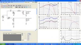
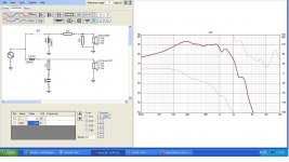
Hi AllenB , I am really sorry for being a Novice at this , using the software for the first time can you please elaborate on how do i get the woofer skating along the pink line attached is response of the woofer without any filters , it has a massive peak from 150hz to 5khz..
Attachments

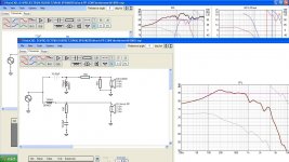
I guess you can start by increasing the value of the inductor until either the 200-900 region comes down to the line, or the response is near 79dB at the crossover frequency.
Then post and we'll see.
Then post and we'll see.
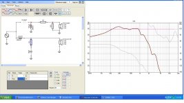
Yes, that's more like it.
The downturn looks kind of flat. I think it needs lifting at the start, and dropping at higher frequencies. It should bend like a knee. Try adjusting the resistor and cap values.
The downturn looks kind of flat. I think it needs lifting at the start, and dropping at higher frequencies. It should bend like a knee. Try adjusting the resistor and cap values.
Great, there's a little too much cut at the crossover frequency. Make the cap just a little smaller and you can move on to the tweeter.
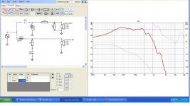
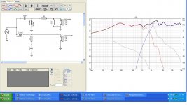

That doesn't look bad. In fact it looks good, a small downward tilt, good phase agreement across the whole crossover band, the breakup peak is down 12dB.
Some extra information. Your inductors have a resistance value tied to them. Lower values either use heavier gauge copper, or a shorter coil (eg by using an iron core). This changes the price. The tweeter is not so critical.
The 6uF cap, you may find 6.2uF to cover this.
The 6uF cap, you may find 6.2uF to cover this.
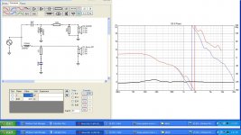
It doesn't, it wraps around. Try inverting both drivers. This will only change how it looks, not how it works.why does that shoot up after 2khz ?
Something that I have seen happen a lot in ported speakers is that they unload below the tuning frequency to combat this problem I have had used a 2nd hpf in active setup at tuning frequency this works wonders , can something similar be done in a passive setup
Some extra information. Your inductors have a resistance value tied to them. Lower values either use heavier gauge copper, or a shorter coil (eg by using an iron core). This changes the price. The tweeter is not so critical.
The 6uF cap, you may find 6.2uF to cover this.
thank you .. will do the same
- Home
- Loudspeakers
- Multi-Way
- 2way passive cross over help