I have two drivers available from RCF, the High Frequency Transducer is ND1411-M and the MiD Bass MB8N251.
I would like to do same test and combine them in a 2 way systems
To have a starting point, can someone tell me the best way to crossover this to drivers.
I appreciate your help.
The HF as Frequency Range : 1500 -20000 Hz
Sensitivity: 109 dB
the MID-BASS: Frequency Range 60 - 3500 Hz
Sensitivity: 96 dB
Attachments
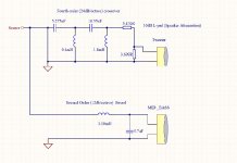
I would try a 4th order 2kHz crossover for the tweeter along with 2nd order crossover to woofer at same freq. Just pulled that from my mind, no calculations so far 🙂
The tweeter also needs at least 10dB or damping.
The tweeter also needs at least 10dB or damping.
Hi Mayuri,
Thanks for the reply,
can you please check if this schematics is what you mention
In the second order crossover the phase shift 180 degrees (reversed polarity)
So I have to reverse the connection of the Mid-Bass is this correct?😕
Thank you for the help.
Thanks for the reply,
can you please check if this schematics is what you mention
In the second order crossover the phase shift 180 degrees (reversed polarity)
So I have to reverse the connection of the Mid-Bass is this correct?😕
Thank you for the help.
Attachments
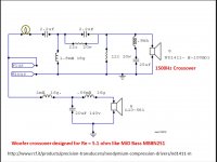
--From RCF website, this compression driver requires a horn.
--The attached RCF crossover should also work with your Re=5.1 ohm MiD Bass MB8N251.
--You may need to add a small value resistor in series with the tweeter to get a good SPL match.
--HF94 90-degree horizontal and 40-degree vertical beamwidth is popular horn for home use.
=======From RCF website
• The ND1411-M is a high performance 1.5-inch diaphragm compression driver with a 1-inch exit throat featuring a single pieces, low compression, radial phase plug.
• Very good linearity in combination with RCF HF94, HF64 and HF101 horns
RCF - ND1411-M
Attachments
Damping for the tweeter 13 dB or more.
It would use 4 order LR filter for both mid bass and tweeter.
It would use 4 order LR filter for both mid bass and tweeter.
--From RCF website, this compression driver requires a horn.
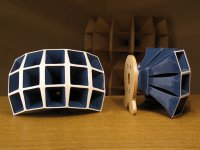
Yes I have this horn that I want to try.
I've been seeing several inductors for the X-over: Air Core coils,Irons Core coils,C Coils,WaX Coils,...
Can you please help me choose the best type of inductor for each function?
Thanks I appreciate the help
Attachments
Air Coil = no saturation at all
In case of iron cores you must calculate the max. power of the coils.
It is not so easy to choose the right coil for each coil in the crossover.
First construct the crossover, post the schematics here.
In case of iron cores you must calculate the max. power of the coils.
It is not so easy to choose the right coil for each coil in the crossover.
First construct the crossover, post the schematics here.
Air Coil = no saturation at all
In case of iron cores you must calculate the max. power of the coils.
It is not so easy to choose the right coil for each coil in the crossover.
First construct the crossover, post the schematics here.
This will be use with a SET amp 25W max
I'm thinking of using the schematic that is posted on the RCF Web Page and
the LineSource posted here

For the low pass, you should choose transformer cores, because of the 600 W power handling of that driver.
Capacitors should be MKP.
Capacitors should be MKP.
In the high pass section, you can use air coils. 2mm coil diameter.
Can you post some information, where want to buy the crossover parts?
Can you post some information, where want to buy the crossover parts?
In the high pass section, you can use air coils. 2mm coil diameter.
Can you post some information, where want to buy the crossover parts?
I'm thinking of using the inductors from Jantzen, here is the link:
https://www.hificollective.co.uk/catalog/inductors-coils/jantzen/html
These speakers will be used to handle low power Amps
So I do not need to build a X-over to deal with 600W of the speakres.
For the low pass of the bass-mid driver:
C Coils or wax coils.
MKP capacitors. Not nessecary for the impedance compensation.
Air coils for the high pass of the tweeter.
C Coils or wax coils.
MKP capacitors. Not nessecary for the impedance compensation.
Air coils for the high pass of the tweeter.
For the low pass of the bass-mid driver:
C Coils or wax coils.
MKP capacitors. Not nessecary for the impedance compensation.
Air coils for the high pass of the tweeter.
Can you tell me, please, what is the role of the two resistances in the high pass
filter?
for the impedance compensation I will use jantzen metallized polypropylene
Thanks for the help
Can you tell me, please, what is the role of the two resistances in the high pass filter?
schematic_post3
The 3.7 ohm and the 5.47 ohm resistors create an "L-Pad".
Info and on-line calculator here
http://www.bcae1.com/lpad.htm
The 3.7 ohm shunt resistor attenuates the 8 ohm (nominal) HF driver by about 10 dB.
The 3.7 ohm in parallel with the 8 ohm HF driver makes a 2.53 ohm load.
The 5.47 ohm series resistor restores the 8 ohm load in that part of the circuit.
Last edited:
I'm trying to figure out, this X-over layout ,what is the role of the two resistances the 22R and 12R are they work as a L-pad ? and the .9mH coil with 25uF cap are they a Zobel Circuit (Impedance Stabilization).
this are the two elements of this schematics that I don't' fully understand.
thanks for the help
this are the two elements of this schematics that I don't' fully understand.
thanks for the help
Attachments

Looks like a notch filter to attenuate part of the freq. the driver likely has a peak around 2-4kz and that helps flatten the response. You can play with the calculator here: mh-audio.nl - Home
The picture you attached is very detailed, thanks for your reply--From RCF website, this compression driver requires a horn.
--The attached RCF crossover should also work with your Re=5.1 ohm MiD Bass fnf MB8N251.
--You may need to add a small value resistor in series with the tweeter to get a good SPL match.
--HF94 90-degree horizontal and 40-degree vertical beamwidth is popular horn for home use.
=======From RCF website
• The ND1411-M is a high performance 1.5-inch diaphragm compression driver with a 1-inch exit throat featuring a single pieces, low compression, radial phase plug.
• Very good linearity in combination with RCF HF94, HF64 and HF101 horns
RCF - ND1411-M
- Home
- Loudspeakers
- Multi-Way
- 2way crossover