Nice! Ben saved a 2sk79 by using a depletion mode FET for the CCS. Otherwise, this looks similar.
BTW, where are you guys getting 2sk79 from?
BTW, where are you guys getting 2sk79 from?
I bought 100 pcs of matched 2SK79 from Japan, and I think that was the last batch, it's now obselete and very hard to find in Japan.
Yet the so-called "matched" by the seller is only Idss@Vds=9 +-10%, that's just point-matching; so I performed curve-matching by myself.
Maybe because 2SK79 is early-generation transistor, its discreteness is clear.
For example, I took N=20 randomly-chosen devices to measure their Idss:

Histogram Statistics:

Curve Tracing of 2 2SK79

Yet the so-called "matched" by the seller is only Idss@Vds=9 +-10%, that's just point-matching; so I performed curve-matching by myself.
Maybe because 2SK79 is early-generation transistor, its discreteness is clear.
For example, I took N=20 randomly-chosen devices to measure their Idss:
Histogram Statistics:
Curve Tracing of 2 2SK79
That is a lot of 2SK79. What are you doing with them?
From an audio point of view I think that the area of interest is up to about 8mA Id and up to about 60V Vds.
Yes, I have seen the SRPP version. I wanted to do something different, with higher voltage.
From an audio point of view I think that the area of interest is up to about 8mA Id and up to about 60V Vds.
Yes, I have seen the SRPP version. I wanted to do something different, with higher voltage.
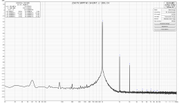
Here's a 1V distortion measurement of the above mentioned SRPP circuit, except with a shunt supply. As Ben mentioned, lower overall distortion and a bit more third in the mix. Its a great sounding circuit, though I've often wanted to hear more of the SIT character. My guess is Ben's circuit would be an ideal approach to sweetening things up a bit.
Attachments
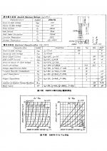
I was looking at the 2SK79 specification sheet yesterday and I realized that I had been ignoring the operating condition that was used for the Typical Electrical Characteristics. Back when I used to play around with tubes, I would start with the typical operating points that were on the specification sheets. I must be losing it in old age.
The 2SK79 specification sheet showed 50V Vds and 4mA Id. So I upped the Vds to 50V and dropped the Id to 5mA and did some distortion measurements and some listening. The distortion at 22.0 Vrms output was 15% lower on the right channel and 20% lower on the right channel. Soundwise, I don't know whether the difference was noticeable. The preamp is probably broken in now and I am really liking the sound.
One thing that was noticeable was that the higher order distortions were a bit higher now. That is probably due to the V+ at 90V and Vd at 50V. Unfortunately the power supply capacitor is only 100VDC rated. My mistake for not paying proper attention to the 2SK79 specification sheet in the first place. But I have now increased the V+ to 95V. I previously had four 20V and one 12V zeners in the voltage reference string and that gave a final voltage of 90V or so. I changed that to four 20V and one 15V zeners plus one blue LED. Final voltage is now 95V.
Now to do some distortion measurements when I stop listening to the music.
Attachments
Last edited:

Hi Ben
Nice work. A buddy and me played with 2sk79 a few years back, from memory, the best operating point was around 40V 2.4mA but that may have been cascoded... Will see if I can dig out the measurements.
Best,
Cv
Nice work. A buddy and me played with 2sk79 a few years back, from memory, the best operating point was around 40V 2.4mA but that may have been cascoded... Will see if I can dig out the measurements.
Best,
Cv
Hi CV, Thanks. If cascoded, the results would be different. I intentionally did not cascode, but wanted the full triode effect.
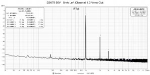
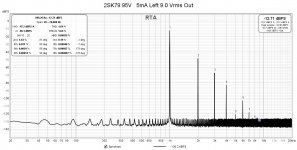
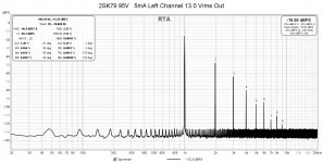
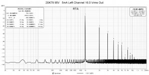
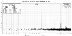
Here are the latest distortion measurements with a 95V power supply, 50 Vds, and 5ma Id. Distortion is lower as I mentioned in post #26. I'm happy with these numbers. I won't be upping the power supply to 100V since I don't want the power supply voltage to be at the electrolytic capacitor's voltage limit of 100V.
Right channel:
Attachments
-
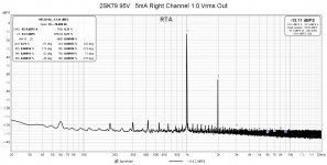 2SK79 95V+ 5mA Right Channel 1.0 Vrms Out.jpg184.1 KB · Views: 168
 -
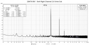 2SK79 95V+ 5mA Right Channel 2.8 Vrms Out.jpg184.8 KB · Views: 182
 -
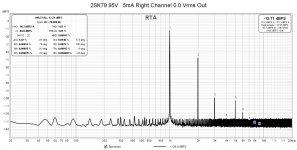 2SK79 95V+ 5mA Right Channel 9.0 Vrms Out.jpg185.7 KB · Views: 140
 -
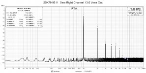 2SK79 95V+ 5mA Right Channel 13.0 Vrms Out.jpg185.3 KB · Views: 136
 -
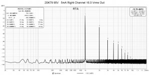 2SK79 95V+ 5mA Right Channel 16.0 Vrms Out.jpg185.4 KB · Views: 139
 -
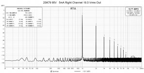 2SK79 95V+ 5mA Right Channel 18.0 Vrms Out.jpg185.4 KB · Views: 130
 -
 2SK79 95V+ 5mA Right Channel 20.0 Vrms Out.jpg185.1 KB · Views: 132
 -
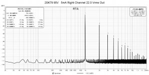 2SK79 95V+ 5mA Right Channel 22.0 Vrms Out.jpg185.4 KB · Views: 145
 -
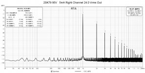 2SK79 95V+ 5mA Right Channel 24.0 Vrms Out.jpg185.4 KB · Views: 165
Left channel:
Attachments
-
 2SK79 95V+ 5mA Left Channel 1.0 Vrms Out.jpg182.2 KB · Views: 111
 -
 2SK79 95V+ 5mA Left Channel 2.8 Vrms Out.jpg184.6 KB · Views: 122
 -
 2SK79 95V+ 5mA Left Channel 9.0 Vrms Out.jpg182.7 KB · Views: 104
 -
 2SK79 95V+ 5mA Left Channel 13.0 Vrms Out.jpg184.5 KB · Views: 106
 -
 2SK79 95V+ 5mA Left Channel 16.0 Vrms Out.jpg184.3 KB · Views: 117
 -
 2SK79 95V+ 5mA Left Channel 18.0 Vrms Out.jpg184.1 KB · Views: 105
 -
 2SK79 95V+ 5mA Left Channel 20.0 Vrms Out.jpg184.3 KB · Views: 99
 -
 2SK79 95V+ 5mA Left Channel 22.0 Vrms Out.jpg184.7 KB · Views: 105
 -
 2SK79 95V+d 5mA Left Channel 24.0 Vrms Out.jpg184.8 KB · Views: 115
Good catch. I hadn't checked the pinout on that datasheet.
*WARNING: 2SK79 Datasheet in post #26 has incorrect pinouts *
Corrected pinouts:
*WARNING: 2SK79 Datasheet in post #26 has incorrect pinouts *
Corrected pinouts:
Attachments
Last edited:

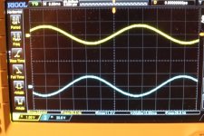
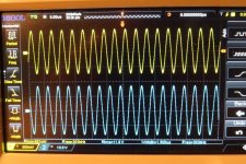
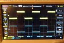
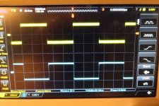
I hooked up my signal generator and oscilloscope today and did some measuring to check the frequency response and gain. While I was at it I also checked out the square wave response.
For frequency response and gain, I inputted a 500mVrms signal and measured the output voltage driving a 20 kOhm resistor load. Typically the output voltage was 11.6Vrms. It did drop to 10.9Vrms at 10 Hz, but the output was still 11.6Vrms when I stopped the high frequency at 300 kHz.
For most of the frequency range the gain was 23.2X or 27.3dB. The low frequency was down 0.54 dB at 10 Hz.
The square wave at both 5 kHz and 10 kHz didn't appear to have any issues (to my eyes, but I'm no expert). 🙂
Attachments
So I spent some time on LTSpice playing with operating points to see if I could lower the distortion. Higher Vds seemed to lower the distortion. As with all simulations models do not always accurately represent real life. In the case of the 2SK79 model that I found and used, the distortion levels in LTSpice were around a factor of ten too low. However the simulations did show trends, whether changes increased or decreased the level of distortion.
So with some information gleaned from LTSpice I tried increasing the 2SK79 Vd. With the 100V electrolytic capacitor on th V+ supply I was limited with what I could do in real life for the moment. I increased Vd from 50V to 65V, and decreased Iq to 3.5mA to keep dissipation within a reasonable level.
Distortion dropped as LTSpice predicted. The only downside was at higher output levels higher order harmonics started to show up. This did not appear in LTSpice so again, LTSpice simulations do not accurately represent real life.
So the next step is to raise V+ to try to get rid of the higher order harmonics at high power output. The existing power supply is good for about 147V so I will use that for V+ and increase Vd to 70V or so. I will need to change the 100V electrolytic though but I will just disconnect it for the initial measurements. I will use the right channel as the test subject as it has higher distortion than the left channel.
By the way, I switched the boards between channels at some point in time. The board in post #2 originally identified as the right channel is now the left channel, and the board in post #7 identified as the left channel is now the right channel. So when comparing those distortion results to subsequent results, their channel identifications should be flipped (post #2 is left channel and post #7 is right channel).
To avoid any confusion, here is a summary:
| THD: 1Vrms | 10Vrms | 20Vrms | |
V+=92V Vd=46V Iq=5mA Left | 0.22% | 1.98% (9Vrms) | 4.97% |
V+=92V Vd=46V Iq=5mA Right | 0.27% | 2.37% (9Vrms) | 5.46% |
V+=97V Vd=50V Iq=5mA Left | 0.17% | 1.64% (9Vrms) | 4.23% |
V+=97V Vd=50V Iq=5mA Right | 0.21% | 1.82% | 4.26% |
V+=97V Vd=65V Iq=3.5mA Left | 0.098% | 0.94% | 2.19% |
V+=97V Vd=65V Iq=3.5mA Right | 0.17% | 1.63% | 3.25% |
Attachments
-
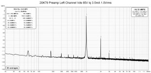 2SK79 Left Channel Vds 65V Iq 3.5mA 1.0Vrms.jpg178.3 KB · Views: 95
 -
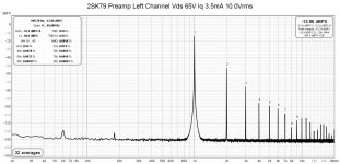 2SK79 Left Channel Vds 65V Iq 3.5mA 10.0Vrms.jpg178.3 KB · Views: 107
 -
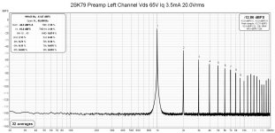 2SK79 Left Channel Vds 65V Iq 3.5mA 20.0Vrms.jpg180.3 KB · Views: 95
 -
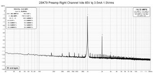 2SK79 Preamp Right Channel Vds 65V Iq 3.5mA 1.0Vrms.jpg179.4 KB · Views: 98
 -
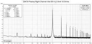 2SK79 Preamp Right Channel Vds 65V Iq 3.5mA 10.0Vrms.jpg181.5 KB · Views: 91
 -
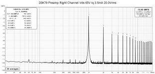 2SK79 Preamp Right Channel Vds 65V Iq 3.5mA 20.0Vrms.jpg181.9 KB · Views: 103
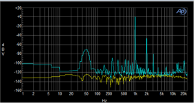
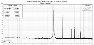
So I increased the right channel V+ to 147V and Vd to 71V. Previously I had already decreased the 2SK79 Iq to 3.5mA when I had increased Vd to 65V, so that remained. This higher voltage was applied to both the 2SK79 and to the DN2540 input and output buffers. However with the increase of V+ from 98V to 147V, I also decreased the DN2540 buffers' Iq from 8mA to 5.5mA to keep their dissipation reasonable.
For the first go around I was going to disable the resistor/zener voltage shunt regulation and apply the full power supply voltage to the board. So that was done, I listened for about half an hour, I liked what I heard, so I went and set everything up to do some distortion measurements. Part way through the measurements, suddenly there was this huge puff of smoke. I immediately shut everything off and after the smoke cleared, I found that the 100V electrolytic at the end of the voltage regulation had vented. I thought I had disconnected it but I hadn't. The direct connection from the regulated voltage was removed but I did not remove the capacitor's connection to the rest of the circuit. So when I connected the 147V power directly to the audio circuit, the electrolytic was still seeing voltage, namely 147V into a 100V capacitor.
The smoke was impressive.
Fortunately there is a local electronics parts shop in Vanvouver, Lee's Electronics, so I was able to get parts quickly. No need to buy online, pay for shipping, and wait for delivery.
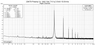
There was no other damage so I was able to fix things quickly and do some more measurements. The increased V+ did make a big difference, and the small bump in Vd possibly helped too. The large amounts of higher harmonics that were previously present had disappeared.
Before I change the left channel board to higher V+, I will try another change to the right channel. Playing with LTSpice some more, I put the buffers' V+ back to 98V and current back to 8mA and the distortion dropped a bit more. Whether that will happen in real life or not, I will find out.
The adventure continues.
For the first go around I was going to disable the resistor/zener voltage shunt regulation and apply the full power supply voltage to the board. So that was done, I listened for about half an hour, I liked what I heard, so I went and set everything up to do some distortion measurements. Part way through the measurements, suddenly there was this huge puff of smoke. I immediately shut everything off and after the smoke cleared, I found that the 100V electrolytic at the end of the voltage regulation had vented. I thought I had disconnected it but I hadn't. The direct connection from the regulated voltage was removed but I did not remove the capacitor's connection to the rest of the circuit. So when I connected the 147V power directly to the audio circuit, the electrolytic was still seeing voltage, namely 147V into a 100V capacitor.
The smoke was impressive.
Fortunately there is a local electronics parts shop in Vanvouver, Lee's Electronics, so I was able to get parts quickly. No need to buy online, pay for shipping, and wait for delivery.
There was no other damage so I was able to fix things quickly and do some more measurements. The increased V+ did make a big difference, and the small bump in Vd possibly helped too. The large amounts of higher harmonics that were previously present had disappeared.
Before I change the left channel board to higher V+, I will try another change to the right channel. Playing with LTSpice some more, I put the buffers' V+ back to 98V and current back to 8mA and the distortion dropped a bit more. Whether that will happen in real life or not, I will find out.
The adventure continues.
Attachments
-
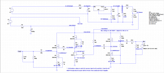 2SK79 V+ 147V Vd 71V Iq 3.5mA.png33.7 KB · Views: 311
 -
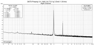 2SK79 Preamp V+ 144V Right Channel Vds 71V Iq 3.5mA 1.0Vrms.jpg180.1 KB · Views: 296
 -
 2SK79 Preamp V+ 144V Right Channel Vds 71V Iq 3.5mA 10.0Vrms.jpg249.1 KB · Views: 160
 -
 2SK79 Preamp V+ 144V Right Channel Vds 71V Iq 3.5mA 20.0Vrms.jpg180.3 KB · Views: 279

The only place I’ve seen them being sold is on eBay from Jim’s Audio. I’m not even sure if he’s selling genuine stuff.Nice! Ben saved a 2sk79 by using a depletion mode FET for the CCS. Otherwise, this looks similar.
BTW, where are you guys getting 2sk79 from?
You guys have to stop building stuff with parts that are not available...this is pure teasing 🤪
If the price isn’t insane I’d like to know of a reliable source, I’d build something for a friend (he pays for the parts)
Thanks
Eric

- Home
- Amplifiers
- Pass Labs
- 2SK79 Preamp - High Gain, High Output, Triode-Like Distortion Profile