2SK79 VFET Preamp - High Gain, High Output, Triode-like Distortion Profile
I really like my Luminaria preamp in combination with my collection of SIT follower amplifiers, but it does not have enough gain since my follower amps do not have volt gain stages and my DAC has very low output voltage. So I had been contemplating what to build that would sound like the Luminaria but with higher gain and voltage output.
Earlier this year a pair of used 2SK79 was available at the diyAudio Swap Meet so I purchased them with the intention of using them in a high gain preamp/follower amplifier front end. I played around a bit with LTSpice and came up with a plan. I am not an EE, don't have the technical expertise, so I just threw some things together and hoped it would work. I took inspiration from the DN2540 buffer in the Luminaria and the B1 Korg's architecture of a triode sandwiched between CCSed JFET input and output buffers.
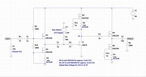
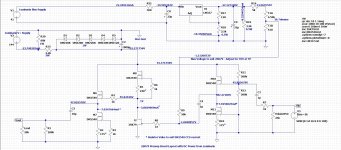
The result is a DN2540 CCS loaded DN2540 input buffer, followed by a DN2540 CCS loaded common source 2SK79 voltage amplifier, followed by a DN2540 CCS loaded DN2540 output buffer. V+ is 90VDC throughout and Iq is 8mA for the buffers and 6mA for the 2SK79. The power dissipation of the 2SK79 is 0.27W compared to the specified maximum of 0.75W at 25 degrees C.
Gain is 28.6dB (27X) according to LTSpice. I will measure to confirm. The Luminaria's gain is 17dB (7X). The distortion is in the same ballpark as my Luminaria, which was measureed at around 0.10% at 1Vrms at 1kHz. The specs for the Luminara state the THD as 0.006% at 1Vrms at 1kHz, but my Luminaria never had such low distortion. However that never did bother me as the distortion was second order dominant. That distortion worked well with the much lower distortion of my various SIT follower amplifiers.
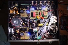
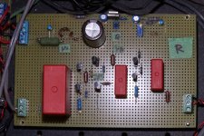
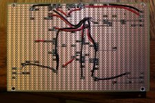
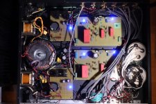
As usual I built the preamp on perfboards. It is housed in my Luminaria chassis, making use of the regulated V+ power supply and the C filtered bias power supply. On each channel's perfboard I added a zener diode shunt to drop the V+ and a LM337 regulator circuit to drop the bias voltage, as the 2SK79 circuit did not need the Luminaria's higher bias voltage. Also remaining are the preamp input and output circuitry. The Luminaria boards and the 2SK79 boards are identical in size and have the electrical connections in the same place, so I can easily swap the boards and have either a Luminaria or 2SK79 preamp in a matter of minutes. After I finished the first board, it replaced the Luminaria right channel and was powered up for tweaking of voltages and operating point, and then preliminary listening with done with the Luminaria left channel still in place for stereo sound.
Both channels are now finished, and I am enjoying the sound.
2022-05-19 Revised schematic here:Revised
2022-08-23 After much tweaking, this is the final circuit:Final Circuit
I really like my Luminaria preamp in combination with my collection of SIT follower amplifiers, but it does not have enough gain since my follower amps do not have volt gain stages and my DAC has very low output voltage. So I had been contemplating what to build that would sound like the Luminaria but with higher gain and voltage output.
Earlier this year a pair of used 2SK79 was available at the diyAudio Swap Meet so I purchased them with the intention of using them in a high gain preamp/follower amplifier front end. I played around a bit with LTSpice and came up with a plan. I am not an EE, don't have the technical expertise, so I just threw some things together and hoped it would work. I took inspiration from the DN2540 buffer in the Luminaria and the B1 Korg's architecture of a triode sandwiched between CCSed JFET input and output buffers.
The result is a DN2540 CCS loaded DN2540 input buffer, followed by a DN2540 CCS loaded common source 2SK79 voltage amplifier, followed by a DN2540 CCS loaded DN2540 output buffer. V+ is 90VDC throughout and Iq is 8mA for the buffers and 6mA for the 2SK79. The power dissipation of the 2SK79 is 0.27W compared to the specified maximum of 0.75W at 25 degrees C.
Gain is 28.6dB (27X) according to LTSpice. I will measure to confirm. The Luminaria's gain is 17dB (7X). The distortion is in the same ballpark as my Luminaria, which was measureed at around 0.10% at 1Vrms at 1kHz. The specs for the Luminara state the THD as 0.006% at 1Vrms at 1kHz, but my Luminaria never had such low distortion. However that never did bother me as the distortion was second order dominant. That distortion worked well with the much lower distortion of my various SIT follower amplifiers.
As usual I built the preamp on perfboards. It is housed in my Luminaria chassis, making use of the regulated V+ power supply and the C filtered bias power supply. On each channel's perfboard I added a zener diode shunt to drop the V+ and a LM337 regulator circuit to drop the bias voltage, as the 2SK79 circuit did not need the Luminaria's higher bias voltage. Also remaining are the preamp input and output circuitry. The Luminaria boards and the 2SK79 boards are identical in size and have the electrical connections in the same place, so I can easily swap the boards and have either a Luminaria or 2SK79 preamp in a matter of minutes. After I finished the first board, it replaced the Luminaria right channel and was powered up for tweaking of voltages and operating point, and then preliminary listening with done with the Luminaria left channel still in place for stereo sound.
Both channels are now finished, and I am enjoying the sound.
2022-05-19 Revised schematic here:Revised
2022-08-23 After much tweaking, this is the final circuit:Final Circuit
Attachments
-
 2SK79 Preamp Schematic.jpg373.9 KB · Views: 1,448
 -
 Half Luminaria Half 2SK79 Preamp.jpg604.8 KB · Views: 1,241
 -
 2SK79 Preamp Board2.jpg666.1 KB · Views: 700
 -
 2SK79 Pramp Board Bottom.jpg761.9 KB · Views: 818
 -
 2SK79 Preamp Board Layout.jpg660.7 KB · Views: 883
 -
 2SK79 Preamp.jpg618.5 KB · Views: 1,288
Last edited:

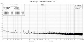
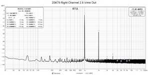
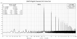
Here are the distortion measurements for the right channel. The output was loaded with a 20k resistor.
Attachments
-
 2SK79 Right Channel 1.0 Vrms Out.jpg181.7 KB · Views: 319
 -
 2SK79 Right Channel 2.8 Vrms Out.jpg182.4 KB · Views: 320
 -
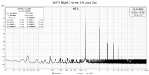 2SK79 Right Channel 9.0 Vrms Out.jpg183.1 KB · Views: 249
 -
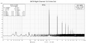 2SK79 Right Channel 13.0 Vrms Out.jpg182.3 KB · Views: 223
 -
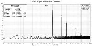 2SK79 Right Channel 16.0 Vrms Out.jpg182.4 KB · Views: 195
 -
 2SK79 Right Channel 18.0 Vrms Out.jpg182.2 KB · Views: 220
 -
 2SK79 Right Channel 20.0 Vrms Out.jpg182.3 KB · Views: 185
 -
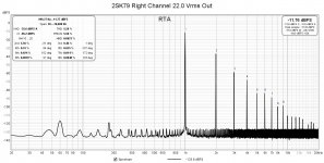 2SK79 Right Channel 22.0 Vrms Out.jpg182.2 KB · Views: 228
 -
 2SK79 Right Channel 24.0 Vrms Out.jpg183 KB · Views: 308
Cool project Ben Mah.
I have these little K79’s installed in a preamp circuit based on Yasui Akira’s SRPP design. It would be nice to try an alternative circuit with them. 👍
I have these little K79’s installed in a preamp circuit based on Yasui Akira’s SRPP design. It would be nice to try an alternative circuit with them. 👍
The SRPP 2SK79 preamp is definitely a different animal. It push-pulls a bit so the distortion is probably lower and more 3rd harmonic.
The preamp seems to be settling in. It must be the $4 Wima 900V 10uF DC Link output coupling caps breaking in. I couldn't resist the low price. No fancy caps in this preamp. 🙂
The preamp seems to be settling in. It must be the $4 Wima 900V 10uF DC Link output coupling caps breaking in. I couldn't resist the low price. No fancy caps in this preamp. 🙂

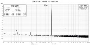
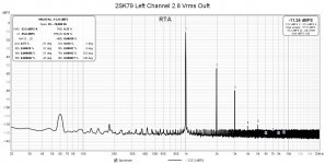
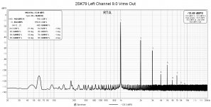
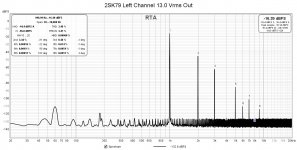
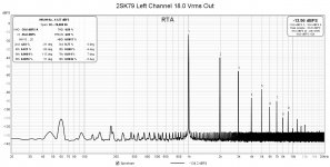
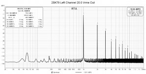
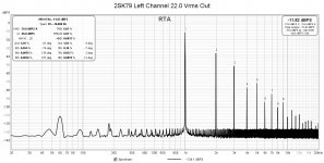
The distortion numbers for the left channel were a bit higher than the right channel numbers. Also the left channel had a bit more 3rd harmonic distortion.
The left channel 2SK79 gave me a bit of a scare at first power up. I had done a quick low voltage Idss test when I received them so I knew that they were functional. However when I first powered up the board I could not get Vds to rise above 2V or so, regardless of the Vgs. The 2SK79 was mounted in a socket so I pushed and wiggled it a bit and I got a momentary high Vds reading. I was also monitoring the current and fortunately the CCS kept the current low the whole time. So I powered down, removed the board, and examined it. What I found was the gate pin had broken off a the base of the 2SK79. The 2SK79s were purchased used and the pins had probably been bent a few times before I received them, and I bent them a bit pushing them into the socket. The source pin was also on the verge of falling off. So what had happened was that with the gate not connected to receive the bias voltage, the drain was wide open and the drain resistance was very low, but the CCS saved the day.
Fortunately I was able to attach new pins. There was a very tiny stub of the pin left at the base of the 2SK79, so I applied a dab of flux and was able to solder a very small gauge lead from a high kOhm 1/4W resistor to the stub. Since the source pin was on the verge of falling off, I replaced that too.
So the 2SK79 survived to play another day.
Here are the left channel distortion measurements:
Attachments
-
 2SK79 Left Channel 1.0 Vrms Out.jpg179.3 KB · Views: 130
 -
 2SK79 Left Channel 2.8 Vrms Out.jpg181.5 KB · Views: 135
 -
 2SK79 Left Channel 9.0 Vrms Out.jpg181.5 KB · Views: 129
 -
 2SK79 Left Channel 13.0 Vrms Out.jpg181.9 KB · Views: 119
 -
 2SK79 Left Channel 16.0 Vrms Out.jpg181.6 KB · Views: 122
 -
 2SK79 Left Channel 18.0 Vrms Out.jpg181.6 KB · Views: 115
 -
 2SK79 Left Channel 20.0 Vrms Out.jpg182.1 KB · Views: 101
 -
 2SK79 Left Channel 22.0 Vrms Out.jpg181.8 KB · Views: 118
 -
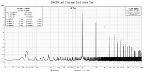 2SK79 Left Channel 24.0 Vrms Out.jpg182.3 KB · Views: 141
Lookin’ good, Ben! I too have tried these parts in SRPP, but would definitely be interested in trying something a bit more sweet.
Hooray! I just tried them in the SCG. They are just awesome.The preamp seems to be settling in. It must be the $4 Wima 900V 10uF DC Link output coupling caps breaking in. I couldn't resist the low price. No fancy caps in this preamp. 🙂
The CCS using depletion FETs is just awesome. It is rock solid and once you set the current, almost nothing can disrupt it. I have not lost a single tube or FET while using the CCS. I did lose a priceless VFET with a choke load and too low Vgs.So what had happened was that with the gate not connected to receive the bias voltage, the drain was wide open and the drain resistance was very low, but the CCS saved the day.
Yup, exactly what I’m saying 😉…… I too have tried these parts in SRPP, but would definitely be interested in trying something a bit more sweet.
Thank you all for following my adventures. My system is sounding mighty fine right now. The sound is similar to the Luminaria but perhaps I think there may be a slight improvement. It's just a feeling that I get. But the Luminaria is a great preamp too. And ZM, yes it has the gain that I want. My TDA1541A dac only has a 65R resistor for I/V duty so its maximum output is only 0.13Vpeak. With my amps that had voltage gain, that was enough for my 103dB speakers. But my single stage front endless follower amps needed the higher gain of this preamp. I was using my ACP+ to boost the voltage when I was using my Luminaria with my follower amps.
Interestingly, when I finally completed the left channel and placed the finished preamp in my system, the left channel sounded weak. The right channel was finished first, and it had played in my system for two days while I worked on the left channel board. Now after two days of play, the left channel sounds full and the sound is balanced. I know that some do not believe in electronics burn-in or break-in but it was noticeable to me in this case, especially since I was able to hear one channel that had time on it alongside the other channel that was just completed.
For me the amount of sugar, as ZM would say, is just right when combined with my SIT followers, which have low amounts of distortion. Also my speakers are 103dB sensitive, so most of the time the system probably is running at less than 1W. I should put my oscilloscope on the speaker output while music is playing just to check.
Wow, 3 coupling caps and that's just the preamp...perfect if you believe semis are a lot more audible than caps.
everyone is having own taste and own way of having fun
Obviously I've got nothing against caps. I believe in equal opportunity - no parts discrimination in my builds. There's more caps in the power supply too.😊
It's DIY, it's entertainment, it's having a good time, and it's for the fun of it. 🤓
It's DIY, it's entertainment, it's having a good time, and it's for the fun of it. 🤓
Very interesting build, Ben!
Coupling cap apart, the most important and ultimate question of life, the universe, and everything remains:
"Would it drive F4?" 😆
🍻
Coupling cap apart, the most important and ultimate question of life, the universe, and everything remains:
"Would it drive F4?" 😆
🍻
Yup, was jokin' 
It's a very nice idea for giving F4 a sweet signature 🙂
Could you please share the source for Wima DC link caps? I think they would be interesting for my B1 R0...
It's a very nice idea for giving F4 a sweet signature 🙂
Could you please share the source for Wima DC link caps? I think they would be interesting for my B1 R0...
Last edited:

- Home
- Amplifiers
- Pass Labs
- 2SK79 Preamp - High Gain, High Output, Triode-Like Distortion Profile