Re: Back in the real world.........
Hi Fred,
There are real instances that you bias near Idss level eg MC phono amp. You can (should) even parallel a few of them to improve the noise performance.
In real life you hardly get 30mA, that's the max Idss for that particular geometry of JFET. However, you do get lots of 22mA Idss from the V group. I do sell JFETs to DIYs and I sell them at all groups.
Y, GR, BL, V, You name it. I stock a lot of V groups as well. At the moment, I don't have 2SK369 in stock. But I have 2SK364-all groups and 2SJ104-all groups. If anyone is interested, just pop me a email.
bty I also have tonnes of 2SK246-BL and 2SJ103-BL, some 2SC5200-O and 2SA1943-O. I can match complementary devices to within 1% as well using my accurate bench top multimeter. I hope this info helps!
James Yung
Praise! Audio🙂
Fred Dieckmann said:Let me know when you run across some Jfets with Idss of 30mA and show me a circuit where they are actually biased that high. The problem is someone assumes these values and then goes and builds a circuit with a couple of milliamps bias current and wonders where the gain went. Most of the Toshiba jfets availble to the DIY are in the GR Ids group and most the circuits I have seen run the device at 1 to 3 milliamps........ Tell me how useful your model will be for these circuits.
I try and design most published circuits for the GR bias group because that is what is available to most. I would be very surprised to see any commercial products designed for anything higher than the BL group........ and I have looked in a lot of products with the K170s and J74s.
Hi Fred,
There are real instances that you bias near Idss level eg MC phono amp. You can (should) even parallel a few of them to improve the noise performance.
In real life you hardly get 30mA, that's the max Idss for that particular geometry of JFET. However, you do get lots of 22mA Idss from the V group. I do sell JFETs to DIYs and I sell them at all groups.
Y, GR, BL, V, You name it. I stock a lot of V groups as well. At the moment, I don't have 2SK369 in stock. But I have 2SK364-all groups and 2SJ104-all groups. If anyone is interested, just pop me a email.
bty I also have tonnes of 2SK246-BL and 2SJ103-BL, some 2SC5200-O and 2SA1943-O. I can match complementary devices to within 1% as well using my accurate bench top multimeter. I hope this info helps!
James Yung
Praise! Audio🙂
Interpreting datasheets
Sorry for not jumping in immediately, and thanks a lot, Fred. Nice link !
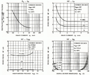
Well, in my case, I need low noise (phono). Looking at the 2SK369 datasheet, noise curves pages (see attached curves), the equivalent input noise (top left) is better for high drain currents, 8 to 10 mA in this case. The noise figure (top right) gives an almost constant NF (@ one frequency) within this ID range. As far as I remember, and correct me if I'm wrong, NF measures the ratio between Input and Output noise. So it should mean that high currents in the Fet generate noise (quite normal if it's thermal noise)... So, if i'm reasoning correctly, I still don't know what current would be the best. Intuitively, around 5 or 6 mA should do the job, and I want to parallel 2 or 3 of these devices... Any hint or error ?
And just one last question to prove I'm completely dumb. I still can't figure out if the so called "signal source resistance" (bottom right) is the impedance of the generator (signal source) or a kind of gate stopper resistor connected to the fet ?
Sorry
Fred Dieckmann said:
Understand what the parameters mean and come to Data Sheets and measurements. The truth will set you free.
http://www.eecg.utoronto.ca/~johns/spice/part3.html#7.8:att'n:
Sorry for not jumping in immediately, and thanks a lot, Fred. Nice link !
Fred Dieckmann said:Let me know when you run across some Jfets with Idss of 30mA and show me a circuit where they are actually biased that high. The problem is someone assumes these values and then goes and builds a circuit with a couple of milliamps bias current and wonders where the gain went. Most of the Toshiba jfets availble to the DIY are in the GR Ids group and most the circuits I have seen run the device at 1 to 3 milliamps........ Tell me how useful your model will be for these circuits.
Well, in my case, I need low noise (phono). Looking at the 2SK369 datasheet, noise curves pages (see attached curves), the equivalent input noise (top left) is better for high drain currents, 8 to 10 mA in this case. The noise figure (top right) gives an almost constant NF (@ one frequency) within this ID range. As far as I remember, and correct me if I'm wrong, NF measures the ratio between Input and Output noise. So it should mean that high currents in the Fet generate noise (quite normal if it's thermal noise)... So, if i'm reasoning correctly, I still don't know what current would be the best. Intuitively, around 5 or 6 mA should do the job, and I want to parallel 2 or 3 of these devices... Any hint or error ?
And just one last question to prove I'm completely dumb. I still can't figure out if the so called "signal source resistance" (bottom right) is the impedance of the generator (signal source) or a kind of gate stopper resistor connected to the fet ?
Sorry

Attachments
One late clarification
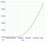
At the moment I posted that model, I was wrongly convinced that is the one that represents one high Idss 2SK369. (I do not use that model often and I messed it with the 2SK363 model I have and which does represents one high Idss 2SK363.) In fact, the model I posted has actually 9.6mA Idss. However, this is just fine with VTO=-.3552. Below is the Id vs. Vgs plot done with MicroCap. So, I would say that the transconductance vs. Id curve would look satisfying. Id vs. Vds plot curves are btw too flat as they are with the bulk of the JFET models (check the few other threads on this topic).
Pedja
Attachments
Re: Re: Re: models from PSpice I bet ......
Hi James, All,
Just stumbled over this thread..
Having looked at a number of JFET datasheets the last days, I'd say the Idss/VGSoff graph is linear in the log/log plots. Same for Idss/Yfs.
I.e.
VGSoff = C * Idss**alpha
Yfs = C' * Idss**beta
For example, the Sanyo 2SK772 datasheet has alpha of about 0.5 and beta of about 0.3
And I assume, 1/beta should always be near 1+1/alpha.
Regards,
Peter Jacobi
Hi James, All,
Just stumbled over this thread..
Praise! said:[...]The transconductance of a common source JFET amp with no source degeneration resistor is 2*Idss/Vgs(off) and Idss and Vgs(off) is linearly related.[...]
Having looked at a number of JFET datasheets the last days, I'd say the Idss/VGSoff graph is linear in the log/log plots. Same for Idss/Yfs.
I.e.
VGSoff = C * Idss**alpha
Yfs = C' * Idss**beta
For example, the Sanyo 2SK772 datasheet has alpha of about 0.5 and beta of about 0.3
And I assume, 1/beta should always be near 1+1/alpha.
Regards,
Peter Jacobi
I use this
.MODEL 2SK369 NJF (AF=100m BETA=65m CGD=19.8997p CGS=24p KF=.002229965f
+ LAMBDA=0.027 VTO=-455m)
http://www.gunthard-kraus.de/Spice_Model_CD/Mixed Part List/Spice-Models-collection/jjfet.lib
Code:
.model J2sk363  NJF(Beta=87.8m Rs=2.238 Rd=2.238 Betatce=-.5 Lambda=1.157m
+               Vto=-.5798 Vtotc=-2.5m Cgd=47.41p M=.3702 Pb=.3905 Fc=.5
+               Cgs=70.37p Isr=1.027p Nr=2 Is=102.7f N=1 Xti=3 Alpha=10u Vk=100
+               Kf=1E-18 Af=1)

.model J2sk369  NJF(Beta=82.61m Rs=1.556 Rd=1.556 Betatce=-.5 Lambda=414.5u
+               Vto=-.3552 Vtotc=-2.5m Cgd=46.72p M=.3623 Pb=.3905 Fc=.5
+               Cgs=70.51p Isr=86.47p Nr=2 Is=8.647p N=1 Xti=3 Alpha=10u Vk=100
+ Kf=74.85E-18 Af=1)- Status
- Not open for further replies.

