Hi,
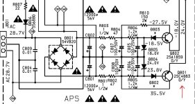
I need to replace the 2SC4883 in a Marantz PM66KI. It's nothing to do with the output section, but used in a regulator that drives auxiliary circuits like the speaker relays, phono board, etc. The schematic is attached.
I feel like I should replace its friend the 2SA1859 too, as these transistors have been roasted for a couple of decades. Other cooked components in this part of the circuit already replaced. The 24V rail is sagging to 10V under load (7V when source direct relay is also engaged) and the transistor doesn't get warm anymore. I think it objected to me re-doing its fatigued solder joints as it was fine until I did that....
So I'm wondering what I can use to replace Sanken 2SC4883 / 2SA1859 with what is currently available.
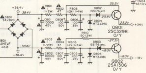
The PM44 has the exact same circuit but uses 2SC3298 / 2SA1306 (Toshiba?) but these don't seem to be available either.
SANKEN 2SC4883 NPN 150V 2A 120MHz 20W TO220
SANKEN 2SA1859 PNP 150V 2A 60MHz 20W TO220
So what about:
ONSEMI MJF15030 NPN 150V 8A 30MHz 36W TO220
ONSEMI MJF15031 PNP 150V 8A 30MHz 36W TO220
ONSEMI MJE15030/1 are the same but 50W
I don't think the transition frequency of the transistor matters much in this application, but I am no expert.
Any advice welcomed.
Glenn
I need to replace the 2SC4883 in a Marantz PM66KI. It's nothing to do with the output section, but used in a regulator that drives auxiliary circuits like the speaker relays, phono board, etc. The schematic is attached.
I feel like I should replace its friend the 2SA1859 too, as these transistors have been roasted for a couple of decades. Other cooked components in this part of the circuit already replaced. The 24V rail is sagging to 10V under load (7V when source direct relay is also engaged) and the transistor doesn't get warm anymore. I think it objected to me re-doing its fatigued solder joints as it was fine until I did that....
So I'm wondering what I can use to replace Sanken 2SC4883 / 2SA1859 with what is currently available.
The PM44 has the exact same circuit but uses 2SC3298 / 2SA1306 (Toshiba?) but these don't seem to be available either.
SANKEN 2SC4883 NPN 150V 2A 120MHz 20W TO220
SANKEN 2SA1859 PNP 150V 2A 60MHz 20W TO220
So what about:
ONSEMI MJF15030 NPN 150V 8A 30MHz 36W TO220
ONSEMI MJF15031 PNP 150V 8A 30MHz 36W TO220
ONSEMI MJE15030/1 are the same but 50W
I don't think the transition frequency of the transistor matters much in this application, but I am no expert.
Any advice welcomed.
Glenn
Attachments
Thanks, the original Sanken parts are not made anymore and do not seem to be on sale in the UK where I live. I do not want to gamble on e-bay suppliers or websites that do not even specify the manufacturer. I need something I can buy from somewhere like Farnell or another trustworthy source.ON Semi MJE15034+35 or MJE243G+MJE253G maybe will work (not recommended) , but better Toshiba 2SC4793+2SA1837 or 2SC5171+2SA1930. I don't know, Sanken 2SC4883+2SA1859 is not problem to find.
I think I found a source now, there's a UK company called Littlediode that seems to have a good reputation and claims to have 2SC4883+2SA1859
Damn.... I will not be buying from them, they sell fakes...
https://www.diyaudio.com/community/threads/avoid-littlediode-uk.308176/
https://www.diyaudio.com/community/threads/avoid-littlediode-uk.308176/

Here's what I do...Hi,
I need to replace the 2SC4883 in a Marantz PM66KI. It's nothing to do with the output section, but used in a regulator that drives auxiliary circuits like the speaker relays, phono board, etc. The schematic is attached.
I feel like I should replace its friend the 2SA1859 too, as these transistors have been roasted for a couple of decades. Other cooked components in this part of the circuit already replaced. The 24V rail is sagging to 10V under load (7V when source direct relay is also engaged) and the transistor doesn't get warm anymore.
Any advice welcomed.
Glenn
I remove R802 & R804 and replace them with wire links (R802 is the most probable cause of your sagging +24V).
I remove the 150R resistor (R810) and install it @ R809 (NOT factory installed).
I remove the wire link adjacent to Q801 which enables R809.
I replace R810 with a 330R/2W wirewound resistor (you'll have to purchase one).
If you have them available, stick TO220 heatsinks on Q801 & Q802.
I leave R805 & R806 as they are when they left the shed @ Heathrow.
So far, Q801 has NOT desoldered itself and my house hasn't burnt to the ground. And I'm listening to a PM-66SE as I type.
Good Luck!
ADDENDUM: I always replace C801 & C802 with non-audiophool capacitors - the factory installed, domed top ELNAs are well past their 'best before' date.
Last edited:
Thanks - all electrolytic capacitors on the main board have been replaced. The big 'uns were domed (but measured fine btw) the whereas the 100/220uF (ELNA RA2) were mostly way off. One of the 100uF ones measured 30uF with an ESR of 22 ohms.
Anyway... R802 seems to measure and look OK, but there is a base/emitter short on the NPN 2SC4883. I wonder if even a TIP31/41 will do here as it's only a zener pass transistor it doesn't need a 100+MHz jobbie does it?
I will replace those resistors although they all measure fine. The only thing that doesn't measure fine is that transistor...
As the maximum operational frequency of Q801 is 0Hz, any NPN transistor capable of dissipating >1.25W continuously into free air without failing/melting is all you require.
Good Luck!
Good Luck!
I wouldn’t say ANY transistor - it is possible to go too big or too slow here. If too slow, output impedance will go inductive. Too big and you may not have enough gain at operating current. With older high power NPNs the beta can be single digits at tens of uA to as much as a mA. TIPs aren’t that bad, but some old switching types can be.
Ok I used MJE15032G. The 24V rail is not sagging anymore, everything looks OK and the amp is working fine.. The speaker relay is back to a loud clunk rather than a feeble click.As the maximum operational frequency of Q801 is 0Hz, any NPN transistor capable of dissipating >1.25W continuously into free air without failing/melting is all you require.
Good Luck!
By measuring the mV across the 1R resistor I can get mA readings in the four relay permutations.
SD = source direct relay, SP = speaker protection relay
+SD +SP = 102mA
-SD +SP = 84mA
+SD -SP = 61mA
-SD -SP = 42mA
I will now think about your other mods. I see from the thread you linked to, and the one that links to (LINK) that you had a few goes at it.
Without reducing the current demands of the supplied circuitry (the relays, etc.) you can't reduce the current through the transistor, so I can only assume you reduced the voltage across it? Wouldn't it sag under load otherwise? Although I think it would be fine if it sagged by a few volts, I'm just trying to work out in your 'rationalised' version what the voltages are at various points.
At the moment (at 100mA) I have R802 (47R) dropping 5V (45 to 38) and the transistor dropping 14V (38 to 24).
Without R802 isn't there an extra 5V going into that 24V zener, with no change in R806?
I'm a bit rusty on my circuit theory, it's been a long time.....
Last edited:
Also in the other thread you added at the end: "And, I also replaced R805 1k5/0.5W and R806 2k2/0.5W (it's what I had immediately available)" but you didn't mention that in this thread so not sure if that was in the final version or not.
I added the HP reference for the benefit of those playing along at home without a PM-66SE. Inserting a headphone jack disables the speaker relay and enables the headphone relay....By measuring the mV across the 1R resistor I can get mA readings in the four relay permutations.
SD = source direct relay, SP = speaker protection relay, HP = headphone protection relay;
+SD +SP -HP = 102mA
-SD +SP -HP = 84mA
+SD -SP +HP = 61mA
-SD -SP +HP = 42mA
You're correct! I should go back to my PM-66SEs and change R805 to 1k8 and R806 to 2k7 or 2k2 (standard E12 values) in order to prevent destruction of the Zeners.At the moment (at 100mA) I have R802 (47R) dropping 5V (45 to 38) and the transistor dropping 14V (38 to 24).
Without R802 isn't there an extra 5V going into that 24V zener, with no change in R806?
Thanks for drawing my attention to that oversight.
There are no traces of rust!I'm a bit rusty on my circuit theory, it's been a long time.....
Good Luck!
I think you did already do that, according to your post on the other thread.
"And, I also replaced R805 1k5/0.5W and R806 2k2/0.5W (it's what I had immediately available)"
Actually, when the load is light, (mute on, source direct off) the 47R is only dropping 2V anyway so you would have only added 2V to that which I think is only an extra 10% of power on the Zener worst case scenario.
I was also wondering why in the original circuit they put that 47R there rather than that 'missing' resistor. The Zener current will vary depending on the load to the transistor because the current through the 47R will change, affecting the voltage across the 1k2. Is it in case of an excessive current draw in the load due to a fault elsewhere, which would cause the drop across the 47R to increase - and the voltage across the 1k2 to decrease - to the point where the Zener is current starved and turns off? I may be talking rubbish here, I don't know what would happen to the output then.
Just to tie this up, here's what I ended up with.
It's Hamish's recipe with new transistors added (one had died anyway) and slightly bigger resistors for the Zener diodes.
I have heatsinks on both transistors and neither get particularly hot anymore.
Everything working nicely.
Thanks for your help @Hamish119


It's Hamish's recipe with new transistors added (one had died anyway) and slightly bigger resistors for the Zener diodes.
I have heatsinks on both transistors and neither get particularly hot anymore.
Everything working nicely.
Thanks for your help @Hamish119
- Home
- Amplifiers
- Solid State
- 2SC4883 / 2SA1859 replacements in Marantz PM66